
Transformer Grounding and Neutral Bonding Requirements
Electrical Concepts And Applications
Published on November 17, 2026 by Staff Writer
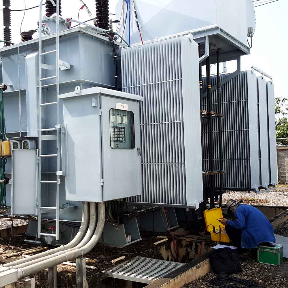
Grounding a transformer involves intentionally connecting a point of its electrical system — typically the secondary neutral — to ground.
This establishes a stable voltage reference and helps define the system’s response to ground faults.
Correct grounding and bonding are crucial for safety and code compliance. This article references the 2026 National Electrical Code (NEC), published by the National Fire Protection Association (NFPA) as NFPA 70.
For your installation, follow the edition and amendments adopted by the local authority having jurisdiction. Next, you’ll learn the key principles behind safe grounding, including grounding transformers, workplace safety rules, electrode resistance, core insulation, and electrode spacing.
Key Principles of Transformer Grounding
Grounding Transformers
In systems without an accessible neutral, such as some delta-connected configurations, you can use grounding transformers to establish a neutral reference. Devices such as zig-zag transformers provide a path for zero-sequence fault currents — the equal, in-phase components of the three-phase currents associated with ground faults. Grounding transformers help the protection system detect and respond to these faults.
Safety and Compliance
Correct equipment grounding and bonding provide a conductive return path for fault current, helping protective devices operate and limit damage. Installations must follow applicable requirements for conductor sizing, connections, and installation methods. Federal workplace requirements also address grounding in the Occupational Safety and Health Administration (OSHA) 29 CFR 1910.304(g).
Grounding Electrode Resistance
The Institute of Electrical and Electronics Engineers (IEEE) standard IEEE 142, published in 2007, specifies a resistance range of 1 to 5 ohms for large commercial and industrial installations. IEEE now lists that standard as inactive-reserved. Use the resistance target established for your project rather than treating this range as a universal code requirement.
Transformer Core-to-Ground Insulation
During initial installation testing, verify core-to-ground insulation, where applicable, using the manufacturer’s specified test procedure, test voltage, and acceptance criteria.
Electrode Spacing
NEC 250.53(A)(3) requires at least 6 feet between multiple rod, pipe, or plate electrodes installed to meet that section. Wider spacing can improve performance: Fluke recommends spacing rods farther apart than their length to reduce overlap between their effective grounding areas. This wider spacing is performance guidance rather than the NEC minimum.
NEC Rules for Separately Derived Systems
NEC 250.30 governs grounding and bonding connections for separately derived systems. Transformers whose secondary circuit conductors have no direct electrical connection to another source’s circuit conductors generally create these systems.
For a solidly grounded secondary, the system bonding jumper connects the grounded conductor — usually the neutral — to the enclosure and equipment bonding path. The grounding electrode conductor connects the derived system to the building’s grounding electrode system at the designated bonding point, using the neutral terminal or a grounding terminal permitted by the section.
Grounding method selection also affects voltage behavior during faults. In an ungrounded system, a single phase-to-ground fault can produce an overvoltage factor of about 1.73 on unfaulted phases, relative to their normal phase-to-ground voltage. Restriking intermittent faults can produce much higher transient overvoltages; a Schweitzer Engineering Laboratories (SEL) paper reports transients exceeding five times nominal system voltage under repeated restriking conditions.
Steps for Safely Bonding Transformer Enclosures
Verify the Low-Impedance Return Path
After bonding the enclosure, verify a continuous, low-impedance fault-current path back to the source. This path enables protective devices to operate. Under NEC 250.4(A)(5), earth cannot serve as the effective ground-fault current path; a low grounding-electrode resistance reading does not establish that the enclosure bonding is adequate.
Use One System Bonding Location
For a typical indoor, solidly grounded, separately derived system, establish the neutral-to-ground bond at one permitted location, usually the transformer or the first system disconnect. Apply the specific exceptions in NEC 250.30(A)(1) only where their conditions are met.
Unintended multiple bonds downstream can create parallel neutral-current paths, overheating, nuisance trips, and code violations.
Keep Downstream Neutral and Ground Bars Separate
In panels downstream of the system bonding point, keep neutral and grounding bus bars isolated. Connect the panel enclosure to the feeder’s equipment grounding conductor, not to the neutral.
Properly Connect Multiple Terminal Bars
When multiple grounding and bonding terminal bars are inside a dry-type transformer enclosure, interconnect them with a bonding jumper whose cross-sectional area is at least as large as the largest conductor connected to either interconnected bar, per NEC 450.12(A).
Apply Electrode-Specific Conductor Sizing
Under NEC 250.66, subsection (A), a grounding electrode conductor connected to rod, pipe, or plate electrodes is not required to be larger than 6 American Wire Gauge (AWG) copper or 4 AWG aluminum, provided it does not extend to another electrode type requiring a larger conductor. Different sizing provisions apply to concrete-encased electrodes and ground rings.
Size System and Supply-Side Bonding Jumpers
The supply-side bonding jumper provides the bonding connection between the transformer enclosure and the first system disconnect enclosure when they are separate. It runs with the secondary circuit conductors.
Size it and the system bonding jumper using the applicable requirements of NEC 250.102(C) and Table 250.102(C)(1). For conductor areas over 1,100 kcmil copper or 1,750 kcmil aluminum, the applicable jumper area must be at least 12.5% of the largest ungrounded conductor area or equivalent area of parallel conductors. Apply the table’s adjustments when conductor materials differ. The unit kcmil means one thousand circular mils, a measure of conductor cross-sectional area.
Pro-Tip: A common but critical mistake is confusing system grounding with equipment grounding and bonding. Each serves a distinct safety function. System grounding connects a point of the electrical system, often the neutral, to earth to stabilize voltage and limit voltage imposed by lightning or surges. Equipment grounding and bonding connect non-current-carrying metal parts into the fault-current return path to the source, helping protective devices clear faults.
Never use the equipment grounding conductor as a neutral or vice versa. Verify that each conductor is properly identified and terminated, and that bonding jumpers and grounding electrodes are installed where required.
Voltage Systems With Solidly Grounded Neutrals
In a solidly grounded transformer system, the secondary neutral connects to the grounding and bonding system without an intentionally inserted grounding impedance. This configuration is common in low-voltage distribution systems, such as 208Y/120 V and 480Y/277 V systems. The connection establishes a stable voltage reference to earth.
Key characteristics of this grounding method include:
Ground-Fault Current and Protective Devices
The low-impedance bonded return path permits high fault currents during a ground fault, allowing properly selected overcurrent protective devices to clear the fault. Available ground-fault currents depend on transformer capacity, transformer impedance, the upstream source, and fault location. Selective operation also depends on protective-device coordination.
Neutral Connections at the Bonding Point
The grounded conductor is the circuit conductor intentionally grounded, commonly the neutral. Use the designated neutral terminal or bus for its connection, and keep it isolated from enclosures and equipment grounding conductors downstream of the system bonding point.
Voltage Stability and Overvoltage Control
This approach stabilizes phase-to-ground voltage relationships and helps control transient overvoltages that can damage insulation. The actual voltage rise during a fault depends on system impedance and grounding effectiveness.
Single-line-to-ground faults account for roughly 70% to 80% of faults on utility overhead distribution systems, according to IEEE. That figure applies to utility distribution lines rather than specifically to building transformer installations.
Controlling Fault Current With Resistance Grounding
Resistance grounding limits fault current during phase-to-ground faults by inserting a neutral grounding resistor (NGR) between the transformer neutral and the grounding system. During a fault, current returns to the neutral through the bonded grounding system and resistor.
In resistance-grounded arrangements, the resistor value depends on the system’s line-to-neutral voltage and the intended fault-current limit. The two primary approaches are low-resistance grounding (LRG) and high-resistance grounding (HRG).
LRG typically permits ground-fault current of 100 to 1,000 A, providing sufficient current for protective relays to detect and trip faulted circuits. An SEL technical paper on impedance-grounded systems describes this range for medium-voltage industrial distribution systems.
HRG commonly limits ground-fault current to 10 A or less, reducing damage from phase-to-ground faults. Continued operation during a first ground fault requires a system designed for that purpose. For the low-voltage arrangements covered by OSHA 1910.304(g)(1)(v)(E), conditions include qualified supervision, ground detection, and no line-to-neutral loads.
Properly designed HRG also controls transient overvoltages from arcing ground faults. The SEL paper describes limits below 2.5 times the normal peak phase-to-ground voltage. These benefits concern phase-to-ground faults; resistance grounding does not eliminate phase-to-phase or three-phase arc-flash hazards.
Grounding Type | Typical Ground-Fault Current | Advantages |
Low-resistance grounding (LRG) | 100 to 1,000 A | Limits ground-fault damage while supporting relay operation and selective clearing |
High-resistance grounding (HRG) | 10 A or less | Limits phase-to-ground fault damage and can permit continued operation during a first ground fault under specified conditions |
How to Verify Grounding Electrode Resistance
To verify transformer grounding, check both the electrode’s connection to earth and the integrity of the equipment bonding system:
- Conduct fall-of-potential testing using auxiliary current and potential probes. Move the potential probe through several positions to identify a stable portion of the resistance curve, following the tester manufacturer’s procedure.
- Use stakeless and selective testing where the grounding arrangement supports them. Stakeless testing requires suitable parallel grounding paths; selective testing uses a current clamp and auxiliary probes to measure an electrode without disconnecting it from the grounding system.
- Employ digital ground-resistance testers suited to the selected method. Compare readings with the project’s specified limits, using automatic frequency selection where available.
- Check electrode requirements separately from project performance targets. Under NEC 250.53(A)(2), a single rod, pipe, or plate electrode requires a supplemental electrode unless its resistance to earth is demonstrated to be 25 ohms or less. This is a supplemental-electrode rule, not a universal maximum resistance for the entire grounding system.
- Consider environmental factors, including soil moisture and temperature, which change seasonally and affect ground resistance measurements. Record these conditions so you can compare readings meaningfully over time.
- Implement periodic testing through a documented maintenance plan, with intervals appropriate to site conditions and applicable maintenance guidance. Ground-testing guidance recommends investigating increases exceeding 20% from previous readings. Treat that trigger as maintenance guidance rather than an NEC requirement.
- Verify system integrity by checking the transformer enclosure or tank, cabinets, and required bonding connections. Check core grounding in accordance with the manufacturer’s instructions. Electrode-resistance testing alone does not verify the continuity of the fault-current return path.