The Grounded Conductor — New Informational Note Article 100 — 2020 NEC
Published on June 29, 2020 by Jerry Durham
In this 2020 Code cycle a new Informational Note now accompanies the term Grounded Conductor where it is defined in Article 100. The Note has been added to help electricians identify functional differences between Grounded and Grounding Conductors.
In defense of all who have struggled with these terms in the past, both grounded conductors and grounding conductors are in fact grounded. They just have different jobs.
Let's now look at these two conductors — their similarities as well as their differences. Let's look at the new Informational Note provided in the 2020 NEC and see if it aids the electrician in distinguishing between these two conductors.
The Grounded Conductor — Part I
Article 100 defines a Grounded Conductor as — A system or circuit conductor that is intentionally grounded.
This definition is undoubtedly correct, but as previously stated, a Grounding Conductor (aka Equipment Grounding Conductor) is ALSO grounded. Therefore, the definition provided for a Grounded Conductor does little to distinguish this conductor from an Equipment Grounding Conductor (EGC).
What about the new Informational Note in the 2020 NEC?
The new Informational Note states- Although an equipment grounding conductor is grounded, it is not considered a grounded conductor.
The new Informational Note reinforces for electricians that Grounding Conductors and Grounded Conductors are both grounded. And that in spite of this, Grounding Conductors are not considered Grounded Conductors by the NEC. But the Informational Note does little else in the way of shedding light on this topic.
To the NEC's credit, the new Informational Note DOES alert the electrician that whenever they encounter the term "Grounded Conductor" in the Codebook they are NOT to interpret it to mean a bare or green-colored Equipment Grounding Conductor (EGC). And that is an important fact.
But it still does not answer the question — if both conductors are connected to ground, why isn't an Equipment Grounding Conductor (EGC) considered a Grounded Conductor? What exactly is a Grounded Conductor beyond the definition provided in Article 100?
The Grounded Conductor — Part II

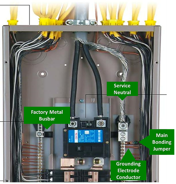
Article 100 told us that a Grounded Conductor is a conductor that is intentionally grounded. This is true. The Grounded (white) Conductor in a branch circuit achieves continuity with ground through its connection with the Service Neutral Conductor in the main panel. The Service Neutral Conductor leaves the utility company transformer with the rest of the service drop and then enters the main panel. The Service Neutral Conductor is then connected by way of a Main Bonding Jumper (MBJ) to the metal enclosure of that main panel, which is then connected by a wire (Grounding Electrode Conductor) to earth.
The grounding electrode used for making a reliable connection with earth can be a copper water pipe, a ground ring, a concrete-encased electrode, or a driven ground such as a copper-coated 8 ft. ground rod; or a combination of these.
The Grounded Conductor — Part III
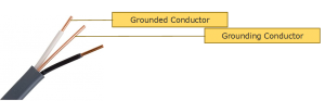
A Grounded Conductor is usually identified with the color white, although it can be gray. If the conductor is size 6 AWG or smaller, it must be solid in color or identified with three continuous stripes of color for the entire length of the conductor. If the Grounded Conductor is size 4 AWG or larger, Section 200.6 permits the conductor to be identified with white or gray only at the terminations.
The Grounded Conductor's job is to serve as the return path for electrical current in a branch circuit, once that current passes through all loads in the circuit and is returning to its source. A Grounded Conductor according to the NEC is a current-carrying conductor. This is important because a bare or green-colored Equipment Grounding Conductor (EGC) is NOT considered a current-carrying conductor. And this is where the difference lies between these two conductors.
A Grounded Conductor (white or gray) and Equipment Grounding Conductor (bare or green) share these characteristics:
- They both are connected to the System Neutral Conductor at the main panel.
- They both are connected to the metal enclosure at the main panel (first means of disconnect.)
- They both are connected to earth.
- They both can carry electrical current.
The difference between these two conductor types is — the Grounded Conductor (white or gray) is designed to safely and continuously carry electrical current. The NEC even refers to a Grounded Conductor as a Current-Carrying Conductor.
On the other hand, an Equipment Grounding Conductor (bare or green) only carries current during a short-to-ground condition, when electrical current is briefly introduced onto normally non-current-carrying metal parts.
Equipment Grounding Conductor (EGC)
The Equipment Grounding Conductor (EGC), required by the NEC and permitted in the form of metal conduit, metal sheathing on metal-clad cable, or bare or green-colored wire-type conductors, is defined in Article 100 as follows:
Equipment Grounding Conductor (EGC) — A conductive path that is part of an effective ground-fault current path and connects normally non-current-carrying metal parts of equipment together and to the system grounded conductor (service neutral conductor) or to the grounding electrode conductor, or both.
So we see the Equipment Grounding Conductor (EGC) is NOT a current-carrying conductor according to the NEC, but is instead an effective ground-fault path that connects non-current-carrying metal parts, such as a metal panel box, a four-square metal box, or a metal stick of conduit to the Service Neutral Conductor, the Grounding Electrode Conductor (GEC), or both.
The Equipment Grounding Conductor (EGC) is designed to allow unwanted fault-current to travel back to its source by way of a low-impedance (unobstructed) electrical path.
This low-impedance path allows the current to quickly meet and exceed the rating of the overcurrent device protecting the circuit, so that circuit breaker or fuse will immediately trip and de-energize the exposed metal parts.
Equipment Grounding Conductors (EGC) Connected to the Service Neutral

On a final note, an observant electrician will wonder: Why is the Service Neutral Conductor attached to the metal enclosure of the first means of disconnect using a Main-Bonding-Jumper (MBJ)?
NEC 250.24 Requires a Main Bonding Jumper (MBJ)
The short answer is — Equipment Grounding Conductors (EGC) for branch circuits are terminated onto a terminal strip in direct contact with the metal panel box. When a short-to-ground occurs on an appliance (or other equipment) somewhere in a home or business, the shorted current rushes back to that metal panel box by way of the Equipment Grounding Conductor (EGC). When the current reaches that terminal strip and metal panel box, if the Service Neutral Conductor is NOT attached to that metal box, the fault current will try to make its way back to its source (the utility company transformer) by way of the Grounding Electrode (e.g. ground rod) driven in the earth. The earth is a poor conductor and current cannot move fast enough through the earth to trip an overcurrent device (under most circumstances.) Therefore, the metal that is not supposed to be energized may remain energized because current cannot ramp up fast enough to trip the 15-amp, 20-amp (or similar) circuit breaker protecting the circuit.
To prevent this, the Service Neutral Conductor that originates at the transformer is connected to the metal panel box through the Main-Bonding-Jumper (MBJ), and this offers a low-impedance path for fault-current to flow back to the transformer, thereby tripping the overcurrent device.
Ground rods are not installed to trip circuit breakers and fuses during a fault condition. Actually, they can't trip these overcurrent devices under most conditions...But that is a topic for another day.