Derating Current-Carrying Conductors for Conditions of Use
Published on August 4, 2020 by Jerry Durham
If you ask a seasoned electrician how many No. 12 AWG conductors will fit into a 3/4" EMT conduit system, you may get a response such as "one more!" While this is amusing (and typically true), there are precautions that must be taken according to the NEC whenever conductors are bundled together in a raceway, cable, or even in a ditch in the earth.
Similar precautions must also be taken where conductors are installed in temperatures above 86°F. Both conditions contribute to heat build-up and poor conductor performance.
We will look at what the 2020 NEC says about these conditions of use by reviewing:
- Section 210.19(A)(1) — Continuous and noncontinuous loads. 125%
- Table 310.16 — Conductor Ampacities
- Table 310.15(B)(1) — Temperatures other than 86°F
- Table 310.15(C)(1) — More than three current-carrying conductors in a raceway, cable, or buried in the earth
Continuous and Noncontinuous Loads — Section 210.19(A)(1)
Section 210.19(A)(1) instructs electricians to size conductors at 100% of the load rating for all noncontinuous loads, plus 125% of the load rating for all continuous loads on the circuit. However, if the electrician must also apply adjustment factors to those conductors from Table 310.15(C)(1) for more than three current-carrying conductors in a conduit, and/or correction factors from Table 310.15(B)(1) for temperatures above 86 degrees Fahrenheit, then the NEC requires us to compare the results from the two requirements and use the larger of the two. In other words, if increasing the conductors by 125% produces the larger conductor, you must use that conductor. But if applying adjustment and correction factors for excessive ambient temperatures and bundling conductors produces the larger conductor, you must use that conductor.
What is the 125% Increase?
Increasing the conductor size 125% for a continuous load serves as an additional heat-sink for the circuit. The larger conductor provides more surface area for heat to be displaced in the circuit and more surface area for heat to be transferred to the surrounding ambient air. The larger conductor takes heat away from the terminals where the conductor is connected. But when the terminals of all components are rated to run 100% of their marked rating, then upsizing the conductor to 125% to serve as a heat-sink is not necessary.
Conductor Ampacity — Table 310.16
Table 310.16 in the 2020 NEC provides conductor ampacities for the wiring we use every day when conditions of use do not force us to deviate from those numbers. Those "conditions of use" usually include ambient temperatures above 86°F, or more than three current-carrying conductors installed together in a raceway, cable, or buried in the earth. Or both.
Table 310.16 is divided into two smaller Tables with copper (Cu) conductors addressed on the left-hand side of the Table and aluminum (Al) and copper-clad aluminum conductors addressed on the right-hand side of the Table. Copper conductors can carry more current than aluminum conductors of the same size.
There are three temperature rating columns provided in the Table: 60°C, 75°C, and 90°C. Most conductors fall into one of these three temperature columns.
Heat is generated inside a conductor as electrical current flows through the conductor. The greater the current flow, the more heat generated in the conductor. The insulation surrounding the conductor, typically thermoset or thermoplastic type insulation, must be rated high enough to withstand that heat. Table 310.16 limits the ampacity of conductors based on their insulation rating. For example a 90°C No. 6 conductor can carry more current than a 60°C No. 6 conductor, not because the wire itself is different, but because the insulation of the 90°C conductor is built to withstand more heat without breaking down. When the generated heat inside the conductor exceeds the insulation rating of the conductor, the insulation surrounding the wire can discolor, become brittle, and may eventually fall off.
If you have ever seen a white grounded conductor that has a brown tint to its insulation, you were looking at a conductor being used at an ampacity higher than its rating.
We understand that heat is generated as current flows through the conductor, and how important it is for a conductor's insulation to be able to safely withstand that heat without breaking down. But another type of heat exists that is equally important to conductor longevity- ambient temperature. Ambient temperature is the air temperature surrounding your electrical conductors after installation. When that is too high, it is bad news for the conductor.
Ambient Temperatures Other than 86°F — Table 310.15(B)(1)
If the temperature surrounding a conductor is above 86°F, the heat being generated inside the conductor during normal use cannot dissipate effectively through the insulation. If the heat cannot effectively escape the conductor, then we must decrease the amount of current flow on the conductor to reduce the heat being generated in the conductor.
This reduction in allowed current flow on a conductor due to ambient temperatures above 86°F is called "ambient temperature correction", and it requires correction factors from Table 310.15(B)(1) to be used in conjunction with the values from Table 310.16.
The correction factors in Table 310.15(B)(1) are percentages, and they are applied to the normal ampacity values provided in Table 310.16 to reduce their value. For example, a THWN No. 6 copper conductor from Table 310.16 is stated to be worth 65 amps. But according to Table 310.15(B)(1), when that same conductor is installed in an ambient temperature ranging between 105°F — 113°F, it is only worth 82% of its value, or 53.3 amps. (65 x .82 = 53.3)
Not only must the electrician be concerned with ambient temperatures degrading and causing poor performance in a conductor, but the electrician must also be wary of installing too many current-carrying conductors together in a raceway, cable, or buried in the earth. Installing more than three current-carrying conductors together in a single raceway, cable, or covered ditch has the same destructive effect on a conductor's insulation as installing conductors in an elevated ambient temperature.
More Than Three Current-Carrying Conductors in a Raceway, Cable, or Earth — Table 310.15(C)(1)
Table 310.15(C)(1) requires conductors to be derated whenever more than three current-carrying conductors are installed together in a raceway, cable, or in a covered ditch in the earth. For example, Table 310.15(C)(1) requires a THWN No.4 copper conductor, normally valued at 85 amps according to Table 310.16, to be derated to 80% of its value when there are 4-6 current-carrying conductors bundled together. The same conductor must be derated to 70% of its normal value when there are 7-9 current-carrying conductors bundled together, and so on. The ampacity of conductors continues to decrease in Table 310.15(C)(1) as the number of conductors bundled together increases.
When more than three current-carrying conductors are installed together in a single raceway, cable, or covered ditch, the ampacity of each conductor must be reduced according to the applicable adjustment factor from Table 310.15(C)(1). Reducing the current flow in each conductor reduces the heat generated in each conductor. Collectively, this reduces the overall operating temperature of the wiring in the conduit system and saves the conductor insulation from premature failure.
A conductor's insulation degrades over time even with normal use. But when the conductor is subjected to temperatures beyond the conductor's rating, that failure occurs much sooner. A conductor used under normal conditions and according to the manufacturer's instructions can provide decades of reliable service.
What is a Current-Carrying Conductor?
Remember, Table 310.15(C)(1) applies only to current-carrying conductors and NOT every conductor is a current-carrying conductor.
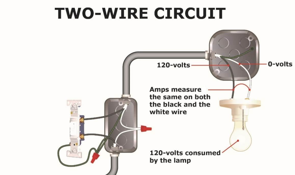
Section 310.15(F) states that a grounding or bonding conductor (typically bare or green in color) is never counted as a current-carrying conductor. However, Section 310.15(E) states that the white grounded (neutral) conductor IS a current-carrying conductor if it carries all of the current (amps) in the circuit, such as a two-wire 120-volt circuit serving a lighting fixture. But when the white grounded conductor is serving as a neutral conductor, where it only carries the unbalanced load between two phase conductors serving the same load, it is not a current carrying conductor. The electrician should study Section 310.15(E) to become familiar with the rules for a neutral conductor installed in a conduit.
How Do We Limit the Current?
Repeatedly, we have stated that a conductor's ampacity is required to be reduced if the conductor is exposed to excessive ambient temperatures or too many current-carrying conductors installed together in a raceway or similar. But how do we reduce that ampacity? How do we limit current flow? Do we get a promise from the customer stating they won't apply more amps to the circuit than we have advised since the conductor has been derated? Of course not. When we say we are limiting the amps or current flow on a circuit or conductors, we simply mean we are reducing the rating of the overcurrent device.
If a conductor is normally worth 50 amps but ambient temperatures require the conductor to be derated to 80%, we simply must reduce the overcurrent device so that it trips at the new ampacity rating of the conductor.
Remember, reducing a conductor's ampacity will not always result in a value that aligns with a standard fuse or circuit breaker size from Table 240.6(A). Fortunately, electricians are permitted to move up to the next standard size overcurrent device in the Table whenever a conductor's rating doesn't align with the standard values from the Table. This is permitted up to and including 800 amps.