Ground Resistance Testing
Published on March 3, 2022 by Dave Varga
When installing an alternating-current electrical service, it must have some type of grounding electrode system. The grounding electrode must have a resistance of over twenty-five ohms or a supplementary electrode must be installed. How do we know if our single ground rod has the proper earth resistance? We don't know unless we have a ground resistance tester and know how to use it. This is not a common hand tool or a daily task, so let's look at how we perform this test, and why we may or may not perform this task.
Section 250.24 — Grounding of Service
Numerous Code sections need to be followed when grounding and bonding an electrical service. For our example today we will assume our location simply needs a single ground rod - or does it? When installing an electrical service, one of our last tasks is to install the 8' x 5/8" ground rod, otherwise known as the grounding electrode. When the electrical inspector arrives to perform the inspection, the inspector needs to know that the single ground rod has an earth resistance of over twenty-five ohms to pass the installation. The electrician on site needs to supply this information, which means a Three-Pole Fall-of-Potential test needs to be set up and shown to the inspector. This test cannot be completed without a ground resistance tester which can cost between $350 and $1350. Once this company-supplied tool is in hand and the inspector is on site, the test will begin.
How to Perform the Fall-of-Potential Test
There are various test methods and procedures that can be used to perform the test, depending on soil conditions and available test area. The most common and widely accepted method is the 3-Pole Fall-of-Potential method.
- First, disconnect the grounding electrode conductor from the ground rod.
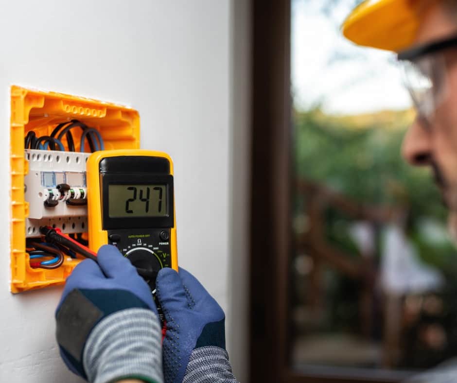
- Second, connect the tester to the exposed top of the ground rod.
- Then, place the two earth stakes in the soil in direct line away from the ground rod, up to 65 feet.
A known current is then generated by the tester between the outer stake and the ground rod while the stake in the middle measures the drop in voltage. The tester uses our basic Ohm's Law to calculate and display the ground rod's resistance to earth. If the Code minimum of over 25 ohms is achieved, the inspector can pass the installation and the job is complete.
Section 250.53(A)2 — Supplemental Electrode Required
For the basic daily installations an electrician performs there is an easier and less time-consuming way to meet the Code minimum. Per Section 250.53(A)2, a single ground rod can be supplemented by an additional electrode such as another ground rod. This supplemental ground rod would be placed no less than six feet away from the other ground rod and bonded together with an equipment grounding conductor. In some areas with dry and sandy soil, the local AHJ (Authority Having Jurisdiction) can require up to three ground rods to be installed if a ground resistance tester is not available to provide ground resistance verification.
Want to know more about Article 250 — Grounding and Bonding? Visit www.jadelearning.com today!