PV Systems: Starting with the Modules
Published on March 10, 2015 by JADE Learning
Over the next 6 blog posts, we will discuss some of the more important code sections pertaining to the electrical installation of the typical roof-mounted, utility-interactive, PV system using a single central inverter. Since the PV system starts with the PV modules, that's where we will start.
Part of the rooftop installation is the module layout. Items such as roof design, plumbing vents, chimneys, and other penetrations can have a big impact on module placement and string configuration. String size (number of modules wired together in series) will determine the overall system voltage, voltage rating of wiring methods, and any fuses used in the source or output circuits. Number of strings wired in parallel with one another will determine the minimum conductor ampacity between the modules and the inverter.
When wiring PV modules in series (to create a series string of modules), voltage is additive while current remains the same. Series = Adds Voltage. When wiring several strings in parallel, the result is the opposite; voltage remains the same while current is additive. Parallel = Adds Current. A PV system with 30 modules wired as 3 strings of 10 modules may require larger conductors than the same 30 modules wired in 2 parallel strings of 15. The best thing to do is to stick to the engineered plan. Any field changes to the design should be resubmitted to the local inspection department for approval.
Since PV modules have no provision for attaching raceways, exposed, open wiring methods are used for the interconnection of the modules. The wiring methods for open conductors under the array can be different, depending on if the PV system is grounded or ungrounded. If installing an inverter for use in a grounded system, then single conductor cable type USE-2 or listed PV wire can be used in accordance with 690.31(C). For an ungrounded system, 690.35(D) allows listed type PV wire to be used within the array but not type USE-2 cable. This is commonly overlooked and it's expensive to find out after a failed inspection that all of the PV source or PV output circuits have to be replaced in an ungrounded PV system because type USE-2 was installed.
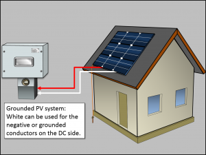
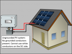
Another consideration is PV source and output conductor identification. There are no special color requirements for the positive or ungrounded conductors for a PV system other than NEC Section 310.110(C). This section just requires that the ungrounded conductors be clearly distinguishable from grounded and grounding conductors. The basic rule in 200.7(A) specifies that white conductors are to be used only for grounded conductors. In a grounded system, there is a grounded conductor, therefore white is permitted to be used for the negative or grounded conductors in a PV source or PV output circuit. In an ungrounded system, there are no grounded conductors. A white conductor cannot be used for the negative conductor in a PV source or PV output circuit. Most installers stick with red for positive and black for negative in ungrounded systems.