Motor Calculations — Part IV: Branch-Circuit Short-Circuit & Ground-Fault Overcurrent Protection
Published on August 14, 2018 by Wes Gubitz

Branch-Circuit Short-Circuit and Ground-Fault Overcurrent Protection is the final article of a four part series. The series is titled "Motor Calculations" and covers the Code and calculations for single general motor applications. In parts I — III we discussed calculating the motor load, the ampacity of the motor branch-circuit conductors, and how to properly size motor overloads. The branch-circuit short-circuit and ground-fault protection devices do not prevent short-circuits or ground-faults. They protect the motor branch-circuit, the wires between the last over-current protection device (OCPD) and the motor, in the event of a short-circuit or ground-fault.

The overloads are designed to protect the motor under overload conditions by removing the motor from the circuit in the event of an over load condition. They must also allow the motor time to clear a typical overload condition, i.e., current during start-up. Start-up current, also referred to as locked-rotor current, is often 6-8 times a motor's running current. The overloads must be sized to allow the motor to start under normal starting conditions. Overloads are not designed to protect the branch-circuit conductors during short-circuit or ground-fault conditions. Properly selected and sized fuses and circuit breakers are used to protect the motor branch-circuit conductors.
The electric motor is expected to perform in some of the most difficult environments under some of the most extreme conditions, and... because of this, it will sometimes fail. One of the most common types of failures is a shorted winding often caused by continuous operation under overload conditions, excessive vibration, over temperature, and/or wet and damp conditions. Winding-to-winding failure, also know as phase-to-phase shorting, is not an uncommon motor failure under these conditions. This type of failure will cause an immediate surge of current, short-circuit current, and should trip the breaker or blow the fuse pending on the type of short-circuit protection used in the motor circuit. Another common failure is when the winding shorts to the frame, a ground-fault will occur and cause the ground-fault protection device to open. Either of these faults will cause a high inrush of current that should open the branch-circuit protection device removing the motor from the circuit.
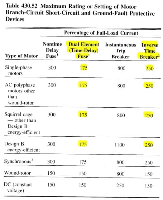
Fuses and circuit breakers are used for motor branch-circuit short-circuit and ground-fault protection. Dual element (time delay) fuses and inverse time circuit breakers are the two most common types used to protect motor branch-circuits. These devices are sized using Table 430.52 Maximum Rating or Setting of Motor Branch-circuit Short-Circuit and Ground-Fault Protective Devices. These protective devices are sized using a "Percentage of Full-Load Current" of the motor. The percentages used for general AC motor circuits is 175% for Time Delay Fuses and 250% for Inverse Time Circuit Breakers. The full-load current is determined using the motor tables found in article 430 as explained in 430.6(A)(1). For general motor applications, current ratings shall be determined based on the values given in Tables 430.247-250. These values shall be used to determine the ampacity of conductors or ampere ratings of switches, branch-circuit short-circuit and ground-fault protection, instead of the actual current rating marked on the motor nameplate.
To calculate the maximum size dual element fuse allowed for a 10 HP, 230 VAC, 3-phase motor, determine the full-load current using Table 430.250. Then, multiply the value, 28A, by 175%, 28A x 1.75 = 49A. Dual element fuses do not come in a standard size of 49A, Table 240.6(A). According to 430.52(C)(1) the rating of the protective device shall not exceed this value, 430.52(C)(1) Rating or Setting for Individual Motor Circuit. Rating or Setting. Unless the calculated value does not correspond to a standard size fuse or circuit breaker, then the next higher standard ampere rating is permitted, 430.52(C)(1) Exception No. 1. This exception allows the dual element fuses to be sized at the next highest standard size, or 50A, 240.6(A).
Determine the maximum rating for a branch-circuit short-circuit ground-fault protective device allowed for an inverse time circuit breaker for a 15 HP, 460 VAC, 3-phase motor. First, determine the motor full-load current using Table 430.250, and apply the percentage value from Table 430.52; 21A x 2.50 = 52.5A. The maximum allowable rating for an inverse time breaker to be used in this circuit is 60A, 240.6(A).
Once again, to determine the maximum allowable size motor branch-circuit short-circuit ground-fault protective device: 1. Use the motor full-load current from the motor tables, 430.247-250. 2. Multiply this value by the appropriate percentage shown in Table 430.52. 3. Then, use the next higher standard size, Table 240.6(A). This last step is in accordance with Exception No. 1 following 430.52(C)(1). There are additional exceptions that apply to the specific protective device when the rating is not sufficient for the starting current of the motor, Exceptions No. 2 (a - d).
These exceptions allow for an additional increase in the rating of the protective device if the rating is not sufficient for the starting current of the motor, if the protective device opens during start-up. Under these exceptions, the rating of the device is permitted to be increased but shall in no case exceed this value. The type of protection used determines the maximum allowable rating with these exceptions, (a) Non-time delay fuses rated 600A or less can be sized up to 400% of the motor full-load current, (b) Time-delay fuses can be sized up to 225% of the full-load current, (c) Inverse time circuit breakers can be sized up to 400% for full-load currents of 100A or less, 300% for full-load currents greater than 100A, and (d) 300% for fuses rated 601-6000A.
Example:
What is the maximum allowable rated time-delay fuse, with exception, that can be used with a 20 HP, 460 VAC, 3 - phase motor if the maximum rating is insufficient for motor start-up?
Answer:
27A x 2.25 = 61A
The maximum allowable rating for this device is 60A.
The calculated 61A shall not be exceeded, so it must be sized down to 60A.
This concludes the series on single motor calculations and the Code. As always, strive to do better and be a better professional today than yesterday. Know your Code.
To learn more, take electrical continuing education online with JADE Learning.