Motor Circuit Calculations — Part I: The Motor Load
Published on March 20, 2018 by Wes Gubitz
As mentioned in our article, Top 2017 NEC Changes in Articles 100 and 110, understanding the electrical trade slang and the language of the Code is necessary to effectively apply the Code. This is especially true when designing motor circuits. The motor circuit has many terms that appear to be interchangeable with some more commonly used terms, but they are not, and understanding how and when to use these terms is key when designing motor circuits that meet Code requirements and permit the motor to operate as expected.
Vocabulary:
Ampacity — 100, 310.15(B)(16)
Continuous Duty — 430.22, 430.32
Continuous Load — 100, 210.19(A)(1)(a)
Full Load Current — 430.6, Table 430.250
Motor Branch-Circuit — 100, 430.31
Overloads — 430.32
Note: Having a basic understanding of these vocabulary words will help you understand how to apply the Code when performing motor circuit calculations.
We measure the power of a motor based on its horse power (HP). Power is the rate at which work is done. A 1 HP motor can be expected to perform the work of 1 horse, or the power to move a 550 lb. load 1 foot in 1 second.
1 HP = (550 lb. * 1 ft.)/sec.
The electrical equivalent of 1 HP is 746 Watts. A motor will, by design, work as hard as you ask, and must be protected from itself. It must be protected from overload, working harder than designed. A properly designed motor circuit, one designed within the parameters of the Code, will perform within the capacity of both the motor's design and the motor circuit, while protecting the motor and the motor circuit conductors.As defined within its Scope, 430.1, Article 430 covers motors, motor branch-circuit and feeder conductors and their protection, motor overload protection, motor control circuits, motor controllers, and motor control centers. Figure 430.1 provides a motor circuit diagram to illustrate the contents of Article 430. Our study will cover those sections that apply to typical or general motor installations. This is a four-part study that will cover basic AC motor circuit calculations:

Part 1 — The Motor Load,
Part 2 — Motor Circuit Conductors,
Part 3 — Overload Protection, and
Part 4 — Short-Circuit Ground-Fault Protection.
The motor circuit is one of the most difficult circuits to understand when it comes to applying all the information provided within the Code for sizing motor circuit conductors, motor overload protection, and motor branch-circuit short-circuit ground-fault protection. You must understand the terminology used in the Code in order to design a motor circuit that performs as expected and within the purpose of the Code, which is the practical safeguarding of persons and property from electrical hazards, 90.1.
A circuit is designed around the load it is to carry. The ampacity of a branch-circuit conductor must be great enough to carry the load, 210.19(A)(1). The overcurrent protection device must be designed to protect the conductor, 240.4. This is nothing new, but how we do it is very different when calculating motor circuits.
You must first understand the motor load. Load is one of those words that is not always what it seems. It is a noun that is also a verb. It is like a cook that cooks. A load loads a circuit. One is the device, the motor load, and the other is what it does to a circuit, it loads a circuit; the greater the load, the higher the current. We must understand the motor load to begin to understand how to size the motor circuit conductors. Conductors are used based on their ampacity. Ampacity is defined as the maximum current, in amperes, that a conductor can carry continuously under the conditions of use without exceeding its temperature rating. Wires are sized based on their load and the environment in which they operate. Paragraph 430.6, Ampacity and Motor Rating Determination, sets the parameters that apply to general motor applications and explains that conductors used with motors are sized according to the allowable ampacity tables in accordance with 310.15(B).
The required ampacity and motor ratings shall be determined as specified in 430.6(A), (B), (C), and (D). For general motor applications, current ratings shall be determined based on (A)(1) and (A)(2). Motor full-load current values given in Tables 430.247 through 430.250 shall be used to determine the ampacity of conductors in motor circuits. The value determined by the appropriate table is the motor load used to determine the ampacity of the motor circuit conductors, the ratings of switches, and branch-circuit short-circuit and ground fault protection. It is not the current rating marked on the motor nameplate.
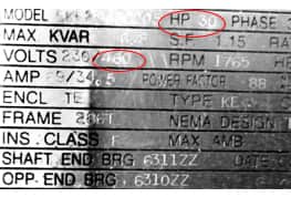
To determine the load, the ampere rating of a 3-phase, 460 VAC, 30 HP motor, turn to Table 430.250. Find the motor horsepower in the left-hand column and locate the correct full-load current under the 460 Volts column — 40 amperes. This is the motor load, the value used to calculate the minimal allowable ampacity of the motor circuit. It is not the 34.5 amps shown on the nameplate. Determining the correct full-load current of a motor is the first step in determining the minimum allowable ampacity of motor circuit conductors.
Understanding where to find the motor load, the full-load current of a motor, is the first step in sizing motor branch-circuit conductors. We will explain how this information is used to calculate the ampacity of the motor branch-circuit conductors in Part 2 — Motor Circuit Conductors. Until then, I encourage each of you to always work toward being a better professional today than you were yesterday. Know your Code.
Learn more at jadelearning.com.