Grounding Versus Bonding: Part 2
Published on August 28, 2018 by Jerry Durham
If you are new to grounding and bonding or a veteran electrician interested in learning all that is available on the subject, I encourage you to come with me now and we will dig a little deeper into these subjects. We will also complete the electrical installation that we started in Part 1, and in the process reveal another real-world grounding and bonding scenario; I feel certain it will add to your growing arsenal of knowledge.

In Part 1: Grounding Versus Bonding, you will recall that we made a clear distinction between grounding, which is to provide a conductive path in the form of an equipment grounding conductor (EGC) for current to flow (to trip a circuit breaker or fuse) in the event of a ground fault condition. And bonding, which is to create continuity between two or more metal electrical components using a conductor or metal conduit, but not necessarily providing a conductive path for current to flow (to trip a circuit breaker or fuse) in the event of a ground fault condition.
In Part 1, the critical difference between the bonding we performed for the three metal boxes, and the grounding we did not perform, was the equipment grounding conductor that we did NOT install to bridge the gap between the metal boxes and the grounded metal electrical panel. Our three metal boxes had continuity with one another, but they were isolated from the electrical panel and had no path for fault current to flow on. They were NOT GROUNDED.
Two Types of Grounding
Before we go any further regarding our installation from Part 1, it must be made clear that in addition to the practice of bonding, there are actually two different types of grounding. The NEC describes both methods as grounding but they really are two different practices.
Let's make it easy:
(1) Grounding, such as using a grounding electrode conductor (GEC) to connect an electrical panel to a driven ground rod, accomplishes two things:
I. It builds an equipotential plane between the metal cased service equipment and the earth, which reduces the potential for electric shock were someone to touch the earth and an energized metal enclosure of the service (short-to-ground occurring on the service enclosure) at the same time. This reduction in potential for electric shock is due to reduced voltage gradient. Voltage gradient and equipotential planes are a different topic, however, and require extensive discussion. So just remember this simple fact about connecting a metal enclosure (such as a panel box) from the electrical service to the earth: In the event of a short circuit (short-to-ground condition on a branch circuit) the connection to earth will not move current fast enough to trip a circuit breaker or fuse. Yes, that's right. This "grounding" path established by attaching a grounding electrode conductor (GEC) from the metal cased electrical panel where bare and green equipment grounds terminate, to the earth of soil and rock below, is insufficient for tripping a breaker or fuse during a fault condition. The earth has too much resistance, and electrical current simply can't flow fast enough to exceed the OCPD trip threshold, most of the time.
II. It diverts lightning strikes so they don't crawl back up the service drop and into the utility company's transformer - causing damage. Instead the lightning is diverted to earth.
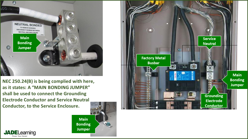
We must remember: it is the connection between the equipment grounding conductors in the branch circuits, to the neutral conductor from the utility company (by way of the main bonding jumper - MBJ) that trips a circuit breaker when there is a fault. The service neutral from the utility company is the perfect "ground". It is terminated at the "zero" point in the utility company's transformer with zero resistance, and that is the point to which all current flowing on the premises is trying to get back to. That "zero" point located within the utility company equipment is intentionally connected to the earth, that is the only reason the earth acts as a ground for a hot wire from the utility company.
(2) Grounding, such as when a metal box or metal cased piece of equipment is connected to the grounding lugs in the electrical panel using an equipment grounding conductor (EGC): This type of grounding has nothing to do with the earth. When you perform this kind of grounding you are connecting metal cased equipment in or outside of a building to the grounding lugs in the panel. That grounding bar is fastened directly to the back of the metal electrical panel and then the panel is connected to the neutral conductor from the utility company by way of the main bonding jumper. That is your path for fault current to flow and that low-impedance path is why a breaker will trip in the event of a fault. Without the main bonding jumper connecting equipment grounds to the utility company's neutral, breakers and fuses would typically not trip, even during a hard fault to ground condition.
Back to our installation!
Now, let's pick up where we left off: At the end of Part 1, we had three metal 4-squares boxes, mounted 10' apart on a non-conductive, wooden wall. Thes three boxes are connected to one another using 10' sticks of PVC (plastic) conduit. We have pulled a green insulated conductor between the boxes, and properly fastened the conductor to the interior side of each metal box with our threaded green grounding screw. We have effectively "bonded" our boxes together.
Now, let's illustrate how dangerous this installation can be - if we fail to GROUND it!
We shall now introduce a 120 volt circuit to our empty metal boxes. First, to get the 120 volt circuit to our boxes, we shall install 30 feet of non-metallic flexible conduit from our first metal box, all the way back to our electrical panel. Remember, this is 30' of NON-METALLIC flexible conduit. Now, with that new flexible conduit installed, we shall take advantage of the path provided back to the panelboard. Let's now push one colored No. 12 conductor and one white No. 12 conductor from the DE-ENERGIZED electrical panel, through our non-metallic flexible conduit, and all the way into our first metal box. We shall now leave the panel area and proceed to our first metal box, where our conductors are now visible. From here, we can feed the colored and white conductors on through the PVC conduit, and into the second and third metal box. Now, that that is complete, let's connect our colored and white conductors to a receptacle, one receptacle for each box, along with an appropriate cover that fits our 4-square box. Now that that is done, let's go back to our electrical panel and terminate our colored conductor onto a new 20a circuit-breaker, and our white conductor onto the neutral bar that is located within that same panel.
Let's close the panel back up and turn the main breaker on so that this panel is energized. We shall now flip that new 20a circuit-breaker on, and we should have a working circuit. Our circuit includes 120-volt working receptacles at each 4-square box. Excellent!
(At this point, I shall mention that our scenario is for informational purposes only, and in no way represents an instructional guide to the proper way to build a code-compliant electrical circuit, or receptacle configuration. As a matter of fact, our example is intentionally in violation of the National Electrical Code, for the purpose of demonstrating the necessity of grounding.)
Now we will introduce an electrical fault into the system that we have just built, that fault will quickly reveal the violation of the National Electrical Code that I just spoke of. A "fault" is, just as it sounds, an electrical "problem" within an electrical component or electrical system. But before we turn that problem loose into our new installation, I want you to take a moment and consider what we have built here. Think about the different parts involved, how they are all connected, and whether or not you feel like we have- at any time during our manufacturing of this system, GROUNDED our metal boxes and receptacles?
Now, as I promised a minute ago- the fault
During the installation here, I want you to imagine that you accidentally nicked the insulation on the colored conductor that is feeding the first receptacle. Nicking that insulation has revealed the bare copper underneath, and that copper is now resting firmly against the bare metal interior side of the first 4-square box. This is the same colored conductor that is currently terminated onto the 120 volt energized (Hot) breaker, back in the electrical panel. So, that energized copper from the conductor is now resting against the conductive metal 4-square box.
Take a moment and visualize what is occurring here. Once you feel confident that you can see the big picture, continue on, and we will see if you have considered all that is happening, and the things that could happen!
Let's now see if your mental picture matches up to the events that are occurring at our electrical installation.
First: The three metal boxes are connected, or "bonded" together by the green insulated conductor that was pulled between the boxes in the beginning. So, whatever "fault" is occurring at the first metal box, by default, must be occurring at the second and third metal box. They are all connected.
Second: The 120-volt energized (Hot) conductor is laying up against the inside of the metal box right now, yet all receptacles are still working, and with no apparent interruption!
Third: The only conductive material that is touching our metal 4-square boxes (other than our new electrical fault caused by the nicked copper wire), is the stripped ends of the green insulated conductor that intentionally bonds these three metal boxes together. Therefore, even though the 120-volt energized portion of the nicked conductor is laying directly against the metal box, there is no path from the box itself, back to anything that is grounded. That is why the receptacles are still working and that is why the breaker has not tripped!
Fourth: Since our three metal boxes are in contact with, (and are therefore now conductively a part of) the energized 120-volt wiring, if a person touches one of these metal boxes, it is the equivalent of touching the stripped end of an energized 120-volt conductor. OUCH!
Finally: Since we recognize that these metal boxes are now the equivalent of a bare 120-volt energized wire, let us also realize that if a barefoot child (or adult) happens to touch these metal boxes, with their bare and unprotected feet planted on the conductive ground (earth), then the voltage potential sitting on these energized metal boxes will now have a grounded path in which to flow, going through that person and back to the earth.
That is a scenario that we never want to experience in the real world.
What do you think we could do to prevent this accident? I will give you a hint, GROUNDING this configuration will keep everyone safe, even during the kind of "fault" that I have described.
To ground this configuration, we would take a green or bare equipment grounding conductor (or a metal conduit) and then fasten it to one of our three metal boxes, while fastening the other end to our electrical panel that is adequately grounded. This would cause the circuit-breaker to immediately trip, when that exposed energized copper wire touches the bare metal of our 4-square box.
When an electrical system is grounded, fault-current produced by a hot conductor touching bare metal, has a path to flow. That unobstructed flow of current through the equipment grounding conductor (EGC), will quickly exceed the tripping threshold of any circuit-breaker, causing it to trip long before someone gets hurt.
It is best to learn these lessons here, in print, so that we can prevent them out there in the real world. Learn more with a JADE Learning electrical continuing education course.