Understanding Motor Branch-Circuit Overcurrent Protection Devices
Published on February 28, 2020 by Wes Gubitz
The primary intent of this discussion is to explain how overcurrent protection devices are determined for single motor branch-circuits. References will be taken from the 2020 National Electrical Code (NEC). These references will apply to general single motor applications for a continuous duty NEMA Design B energy efficient motor, unless otherwise noted.
Article 430 provides a one-line diagram, Figure 430.1, that shows the parts of the motor circuit and where to find the information on each part. A basic understanding of how the motor branch-circuit is designed will help to understand how the motor branch-circuit is protected throughout the range of overcurrents, overloads, short-circuits, and ground-faults. The diagram shown below, Fig. 1, will help identify the components of the motor branch-circuit as they are discussed.
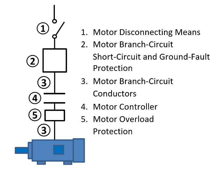
Fig. 1 The Motor Circuit
The motor overload protection device, #5, protects the motor and branch-circuit conductors from excessive overloads during motor operation and in the event the motor has trouble starting, 430.31. The motor branch-circuit short-circuit and ground-fault protection device, #2, protects the motor from these fault currents.
Motor overload devices do not respond immediately to the over current conditions from typical motor operation, brief overload conditions, or motor start up when inrush current can be anywhere from 6-8 times the full load current. The motor overload device protects the motor and the branch-circuit conductors. The overloads are typically sized 115% or 125% of the nameplate full-load rating of the motor and up to 130% or 140% with exceptions, 430.32(A)(1), 430.32(C), 430.6(A)(2). The motor branch-circuit conductors shall have an ampacity of not less than 125 percent of the motor full-load current rating, as determined by 430.6(A)(1) for a single motor used in a continuous duty application 430.22. Reference 430.6(A)(1) states that the ampacity of the motor branch-circuit conductors is determined using the values given in the motor full-load current tables found at the end of Article 430. Reference 430.6(A)(1) also states that these tables, Tables 430.247-250, are used to determine the ampere ratings of switches, branch-circuit short-circuit and ground-fault protection.
The motor full-load current table and Table 430.52 are used to determine the maximum rating of the branch-circuit short-circuit and ground-fault protection. Any one of four overcurrent protective devices can be used as the short-circuit and ground-fault protecting device: Nontime Delay Fuses, Dual Element (Time Delay) Fuses, Instantaneous Trip Breakers, or Inverse Time Breakers. You must know the motor type, horsepower, and supply voltage to use the tables to find the full-load current value for the motor.
Reference 430.52(B) establishes one additional rule that applies to the motor branch-circuit short-circuit and ground-fault protective device, the device shall be capable of carrying the starting current of the motor. The starting current for typical AC induction motors can be 6-8 times the full-load current. The maximum rating of the short-circuit ground-fault protective device is determined using the motor full-load current times the percentage shown based on the device selected, with several exceptions, 430.52(C)(1) and 430.52(C)(3).
The first exception applies to all four of the protective devices. If the values calculated using the maximum percentage allowed do not correspond to a standard size or rating for fuses and non-adjustable breakers the next higher size can be used, 430.52(C)(1) Exception No. 1. An instantaneous trip circuit breaker can only be used if it is adjustable and part of a listed combination motor controller, 430.52(C)(3).
The second exception concerns whether or not the selected protective device can carry the starting current of the motor. If the rating of the protective device is not sufficient for the starting of the motor, apply the corresponding exception from 430.52(C)(1) Exception No. 2 or 430.52(C)(3) Exception No. 1.
Table 430.52 Maximum Maximum with Exception
Nontime Delay Fuse 300% 400% (not to exceed)
Dual Element (Time Delay) Fuse 175% 225% (not to exceed)
Instantaneous Trip Breaker 1100% 1700% (not to exceed)
Inverse Time Breaker 250% 400% (not to exceed)
Note: Percentages shown are for circuits using Design B energy efficient motors.
The time delay fuse and the inverse time circuit breaker are the more commonly used motor branch-circuit short-circuit ground-fault protecting devices. They allow the motor starting current time to cycle from locked rotor to running speed without blowing or tripping. The nontime delay fuse and the instantaneous trip breaker respond to changes in current instantly, or with minimal delay, and will often blow or trip during motor start up due to the high in-rush current. The varying percentages listed in Table 430.52 consider these individual characteristics.
The motor branch-circuit is protected from the full range of currents using two overcurrent protection devices, the motor overload protection device and one of four types of short-circuit ground-fault protection devices. The rules are varied depending on the motor and the devices selected, but easier to understand and apply once there is an understanding of the currents associated with the AC induction motor.
Taken from 2020 NEC, Annex D, Example D8:
Determine the motor circuit conductors, overload protection, and short-circuit and ground-fault protection for one 25-hp, 460-V, 3-phase, squirrel-cage motor, nameplate full-load current 32A, Design B, and Service Factor 1.15.
Conductor Ampacity
The full-load current value to determine the minimum required ampacity is obtained from Table 430.250, 430.6(A).
For a 25-hp motor, 34A * 1.25 = 43A.
Motor Overload Protection
Where protected by a separate overload device, the motor is required to have overload protection rated at not more than 125% of the nameplate full-load current, FLA, 430.6(A) and 430.32(A)(1).
For the 25-hp motor, 32A * 1.25 = 40A.
Where the separate overload device is an overload relay (not a fuse or circuit breaker), and is not sufficient to start the motor or carry the load, the trip setting is permitted to be increased 140%, 32A * 1.4 = 44.8A, 430.32(C).
Branch-Circuit Short-Circuit and Ground-Fault Protection
The rating of the overcurrent protection device depends on the type selected in accordance with 430.52 and the value from Table 430.250.
- Time Delay Fuse: the fuse rating is 175%, 1.75 * 34A = 59.5A, 60A is the next higher size standard fuse rating, 240.6 and 430.52(C)(1) Exception No. 1. The fuse is permitted to be increased, with exception, but shall not exceed 225%, 430.52(C) Exception No. 2(2). A standard 70A fuse rating does not exceed the 225% rating, Table 240.6(A).
- Inverse Time Circuit Breaker: the breaker rating is 250%, 2.5 * 34A = 87.5, 90A is the next higher size standard rating, 240.6 and 430.52(C)(1) Exception No. 1. The breaker is permitted to be increased, with exception, but shall not exceed 400%, 430.52(C) Exception No. 2(3). A standard 125A breaker rating does not exceed the 400% rating, Table 240.6(A).