Motor Calculations — Part III: The Motor Overload
Published on July 2, 2018 by Wes Gubitz
This is the third part of a series designed to help explain how to properly calculate motor circuits. In Part I: The Motor, we demonstrated how to determine the motor load for general motor applications using 430.6(A)(1) which states that table values shall be used to determine the ampacity of conductors... instead of the actual current rating marked on the motor nameplate. The tables used most often to determine motor full-load current are tables 430.248 for Single-Phase AC Motors, and 430.250 for Three-Phase AC Motors.
In Part II: Motor Circuit Conductors, we considered how to properly size a typical motor branch circuit using the motor load as determined with the appropriate table and then multiplying that number by 1.25, reference 430.22. A continuous duty motor is treated as a continuous load, a load where the maximum current is expected to continue for three hours or more. Continuous loads have a multiplier of 125% applied when sizing branch circuits and over-current protection.
Motor Overload Protection
Use the appropriate motor table instead of the actual current rating marked on the motor nameplate when determining the motor full load current and the motor branch circuit conductors for general motor installations, 430.6(A)(1). The motor's full-load current, the nameplate FLA, is used to calculate separate motor overload protection, 430.6(A)(2): Separate motor overload protection shall be based on the motor nameplate current rating. Motor overload protection is necessary to protect the motor and to help ensure the motor performs as expected.
Continuous duty motors are protected against overload by a separate overload device sized between 115% and 125% of the motor nameplate full-load current, FLA. Motor manufacturers have designed several types of separate overload devices with sensing elements that will "trip" when the motor is overloaded. The overload device must trip when needed but allow the motor to start and carry the designed load. The overload device cannot trip, or cause the motor circuit to open the motor branch circuit conductors, during start up, and the overload device must allow the motor to carry the load, to operate at full running current, 460.32(C).
Separate overloads are sized according to 460.32(A)(1): Motors marked with a service factor 1.15 or greater and marked with a temperature rise of 40°C or less are sized at 125% of the nameplate FLA, and all other motors are sized at 115% of the nameplate FLA. The service factor, SF, and the temperature rise will be marked on the motor nameplate if applicable. Overloads can be a rating higher than that determined by 430.32(A)(1) if the sensing element or setting of the overload device selected in accordance with 460.32(A)(1)... is not sufficient to start the motor or to carry the load. The trip current must not exceed 140% of the motor nameplate FLA for motors marked with a service factor 1.15 or greater and marked with a temperature rise of 40°C or less, and 130% for all others, 430.32(C).
Test your knowledge

Using the nameplate above:
- What is the horsepower?
- What is the FLA, nameplate full-load current, for this motor with 460V applied?
- What size overloads are required?
- What is the maximum size allowed if the overloads trip while carrying rated load?
Answers with explanations:
- This is a 5 HP 3 phase motor. See information in block next to the "H.P.".
- The full-load current is 7A at 460V. The " / " indicates that the motor can operate at more than one line voltage value. Most 9-lead, 3-phase motors are "dual-voltage" motors. This means that they can be wired to operate using Low or High Voltage, typically 230V / 460V. This motor will operate using 208-230V and 460V. The current follows the same layout, 14.8-14A, 14.8A at 208V, 14A at 230V, and 7A at 460V.
- With a line voltage of 460V and a full-load current of 7A, with a Service Factor of 1.15 and a temperature rating of 40C, the overloads are sized at 8.75A. The overloads are determined using 125% of the FLA, 7A x 1.25 = 8.75A.
- The maximum allowable size for the overloads is 9.8A. The overloads can be sized at 140% of the FLA if the overloads trip at rated load or will not allow the motor to start, 7A x 1.4 = 9.8A.
A typical induction motor will exceed its nameplate FLA when using across the line starting methods and often during normal operation. This will happen at start-up and when the load the motor is carrying, or driving, exceeds the designed horsepower rating of the motor. Most induction motors will have a starting current of 6-8 times the running current, the full load current, FLA. This inrush current is often referred to as locked rotor current and must be taken into consideration when designing motor circuits, especially when voltage drop is a concern.
The locked-rotor current can be determined using the nameplate Locked-Rotor Indicating Code Letter marked on the motor nameplate and applying the information in accordance with Table 430.7(B), Locked-Rotor Indicating Code Letters. Using the Code letter with the multipliers found in the Table will allow you to calculate an expected "min-max" locked-rotor current (LRC). For example: the multipliers for a motor with a Locked-Rotor Indicating Code Letter of "K" are 8.0-8.99. This means that this motor will have between 8 and 8.99 Kilovolt-Amperes per Horsepower with Locked Rotor. A 10HP, 460VAC, three-phase motor will have between 100-113A of LRC.
Apply the Power Formula using the information given: I = P / E, Current is equal to Power divided by Voltage.
A = 10HP*8KVA/460V*1.732
A = 80,000VA/797V = 100A.
This is the minimum expected LRC, and 113A is the maximum expected LRC using a multiplier of 8.99KVA. A typical 10HP, 460V, three-phase, K coded motor has a FLC of 14A, and LRC of 100-113A.
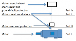
Part I and Part II of this series explained how to determine the motor load used when sizing motor branch-circuit conductors and how to perform the calculations necessary to size the motor branch-circuit conductors. Part III: The Motor Overload, explains how to properly size overload protection for a typical motor installation using separate overload protection, and Part IV will discuss how to properly size motor branch-circuit, short-circuit and ground-fault protection. Until then, I encourage each of you to work toward being a better professional today than you were yesterday. Know your Code.