Duct Leakage Tests
Air-Conditioning and Refrigeration Systems
Published on February 1, 2021 by Reggie Hucks
The International Code Commission (ICC) mandated HVAC duct leakage testing for the first time in the 2009 International Energy Conservation Code (IECC). Since the first leakage test requirement was rolled out, extensive testing procedures and equipment have remained in the Code. Obviously, the scope of the IECC is to conserve energy. Leaking conditioned air to unconditioned spaces is wasteful and unnecessary. There are many duct sealing systems available that will fill most of the small openings around duct fittings. To seal ducts and conduct a leakage test, a HVAC contractor, engineer, or HERS rater use these specialized tools and methods.
Duct Leakage Equipment
Metal duct sealing systems range from paste mastics to putty filled tape. Proprietary sealing tapes are also made for fiberglass duct systems. There are industry manuals and instructional videos available for proper application of these products. For leakage tests, the following methods and materials are used for compliance.
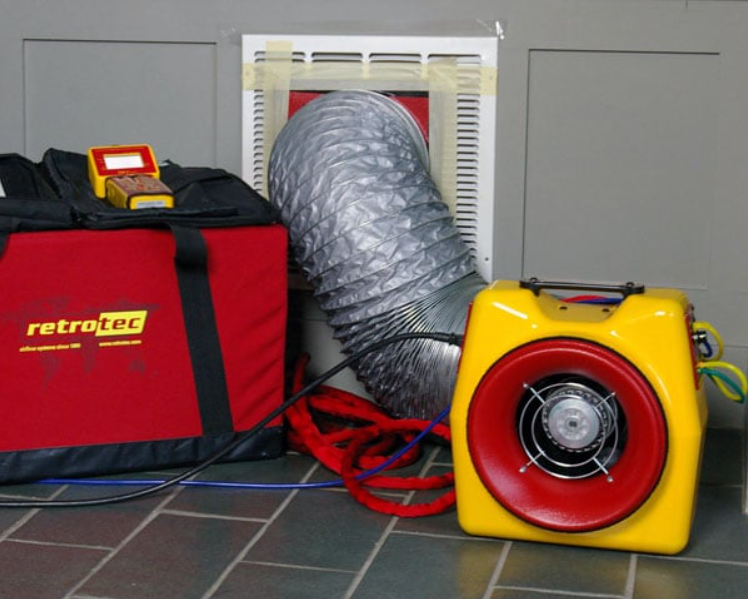
An application, known as the total duct leakage test, creates a negative pressure condition on the duct system, and air handler if installed. By applying negative pressure, it is easier to determine the amount of air leaking through the system when measured at strategic locations. If a strong positive pressure was applied, quantifying the volume of leakage would be more difficult. This test is done with a specific fan, air measuring equipment, and tape for sealing registers and grills. Brands such as TEC Ductblaster, Oriflow, and Retrotec have the technical support that meets the Code requirements for testing.
Duct Leakage Criteria
The leakage test must meet the following criteria:
If the test is done on the "rough-in" stage of the HVAC installation, total duct leakage cannot exceed a 3% leakage rate or 3 CFM per 100 square feet of conditioned floor area. If an air handler is included in the "rough-in" leakage test, the total air leakage cannot exceed 4 CFM per 100 square feet of conditioned area (4% leakage).
Here is an example of how a leakage test works:
A fan depressurizes the duct system to -25 pascals. The volume of air moving through the fan is measured. This air measured is the amount pulled through leaking cracks in the duct system. The number, generated under -25 pascals of pressure, is known as CFM@25. This number is used in the following calculation.
80 CFM moves through the ducts when put under the negative pressure of 25 Pa.
80 is therefore the measured CFM@25.
The house has 2000 square feet of conditioned floor area.
80 (CFM25) X 100 sq. ft. of conditioned floor area = 8000.
8000 / 2000 sq. ft. of total conditioned floor area = 4 CFM.
This can be further calculated as a 4% leakage rate (4 /100). As stated earlier, a 4% leakage rate would only be acceptable if the air handler was installed in the duct system at the rough in stage.
Conclusion
Once the test is done, the system either passed or failed. If passed, the information is put on an energy certificate that is placarded on the house. If the test failed, all HVAC connections are checked and resealed where required. Contractors usually know where problem areas are and work on them first.
A well-sealed duct system with an energy efficient heat pump or furnace can pay back big dividends in reduced energy cost. When an installed system meets these requirements, our carbon footprint is lower, and our profession is a little greener.