PV Systems: Point of Interconnection
By: JADE Instructor | May 29, 2015
A PV system is useless until it gets connected into the premises wiring system. NEC section 690.64 states that the point of connection for a PV system shall be in accordance with section 705.12. Article 705 provides the rules on how an electric power production source, such as a PV system, can be connected in parallel with the primary source of electricity (utility power in this case).
We covered the new interconnection rules related to busbars and conductors in our August, 2014, blog post on PV Interconnections.
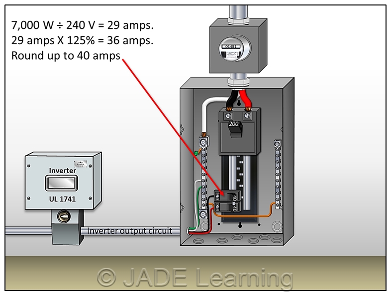
Image 1. Inverter Output Circuit.
In this article, we will be discussing the rules on the backfed circuit breaker used in a utility interactive PV system.
First we have to select the proper size circuit breaker that the inverter output circuit conductors will be backfeeding in the panelboard. The term “inverter output circuit” refers to the AC conductors between the inverter and the point where they interconnect with the premises wiring system (See Image 1). Section 705.60(B) requires both the inverter output circuit conductors and the backfed overcurrent device to be “not less than” 125% of the inverter’s continuous output current rating. This value can be found on the inverter nameplate (See Image 2), but most inspectors or installers will simply divide the wattage of the inverter by the applied voltage to find the answer.
Image 2. Maximum Output on Inverter Nameplate.
This method is more accurate since many inverters can be used in multiple voltage configurations and the value listed on the inverter nameplate is often based on the lowest voltage with which the inverter is compatible. So, based on the 7,000 watt inverter in Image 2 (at 240 volts), we can derive the following: 7,000 W ÷ 240 V = 29 amps (continuous output current rating). 29 amps X 125% = 36 amps. We have just determined that the minimum size circuit breaker required to interconnect the inverter output circuit to the premises panelboard is 36 amps. This is not a standard size according to section 240.6(A). The last sentence in 705.60(B) allows the 36 amp value determined above to be rounded up to the next standard size overcurrent device which is 40 amps (See Image 3).

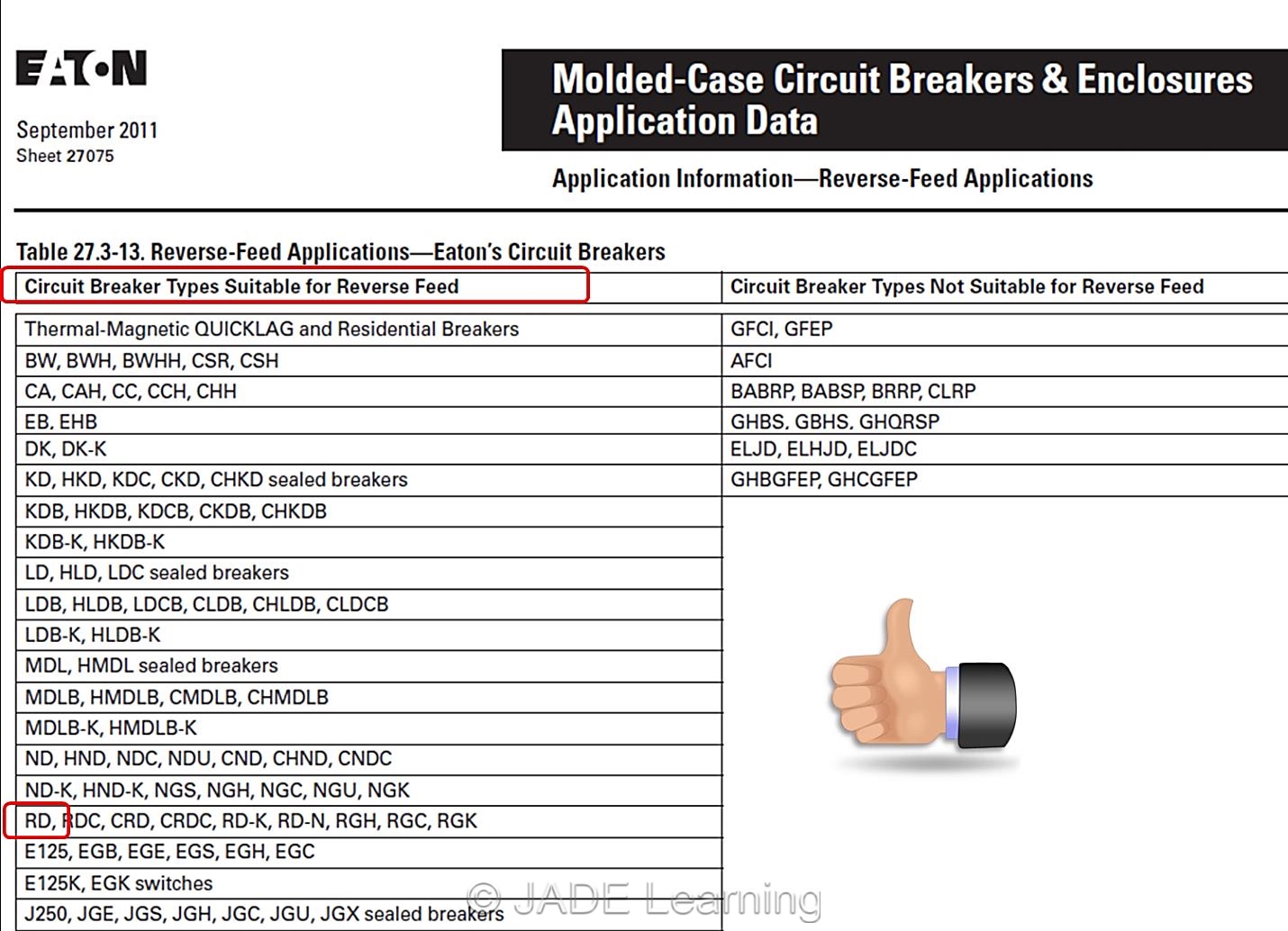
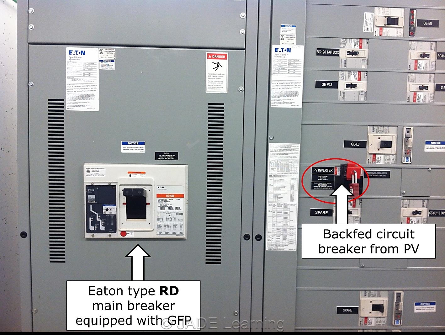
Be mindful of 705.32 when ground fault protected (GFP) circuit breakers are present. This section requires the point of interconnection to be made on the supply side of the GFP breaker unless there is ground fault protection for equipment from all ground fault current sources. Basically, if our PV system has ground fault protection as required by 690.5 or 690.35, and the service or feeder disconnect has ground fault protection where required by 230.95 or 215.10, then we have established ground fault protection for equipment from all ground fault current sources and can connect the inverter output circuit to the premises wiring system on the load side of a GFP breaker. There is one catch though; most GFP circuit breakers are not suitable for reverse feed applications. Any time a circuit breaker equipped with GFP will be backfed, check with the breaker manufacturer to verify it is listed for backfeeding (See Images 4 and 5).
Ready to learn more about PV? Sign up for one of our JADE Learning electrical continuing education courses.
Image 4. Backfed Circuit Breaker.


Great,work. I appreciate your effort that improve my Elec.knowledge.