PV System: Marking and Labeling
Published on July 6, 2015 by JADE Learning
There are many PV system marking and labeling requirements in the NEC. Some markings will be factory applied as required by the product listing and others must be field applied by the installer.
Certain labels can be required on raceways and enclosures while other labels will be needed at DC disconnects that specify values like the maximum system voltage and system current. Here is a quick summary of PV system marking and labeling requirements.
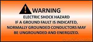
Section 690.5 covers the ground fault detection/interruption for the PV system and requires a warning label on the utility-interactive inverter or near the ground-fault indicator at a visible location. Most often, these labels are applied on the inverter by the manufacturer. See Figure 1.
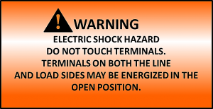
Section 690.17(E) covers disconnection requirements and specifies that a warning label is needed if all of the disconnect terminals can be energized in the open position. See Figure 2. This is often the case for DC feeder disconnects that are subject to backfed direct currents from other PV output circuits on larger PV systems but generally is not an issue for smaller PV systems where DC feeders are not installed with grid tied systems. The utility-interactive grid-tied inverter will de-energize if utility power is not present or when the AC disconnect is opened and therefore the disconnect switch will not have all terminals energized while in the open position.
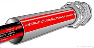
The warning label required by section 690.31(G)(3) is for wiring methods and enclosures that contain PV power source conductors. This includes exposed raceways, cable trays, boxes, and even conduit bodies, in which any of the available conduit openings are unused. This label must have white capitalized letters at least 3/8 inch tall on a red reflective background and be spaced not more than 10 feet apart. See Figure 3.
For ungrounded systems, section 690.35(F) requires each junction box, combiner box, disconnect, and device containing energized, ungrounded circuits that may be exposed during service to have the following label. See Figure 4.

Section 690.53 requires the following items to be labeled (by the installer) on the PV system disconnecting means:
- Rated maximum power-point current (IMP)
- Rated maximum power-point voltage (VMP)
- Maximum system voltage (VOC)
- Maximum circuit current (ISC)
- Maximum rated output current of the charge controller (if installed).
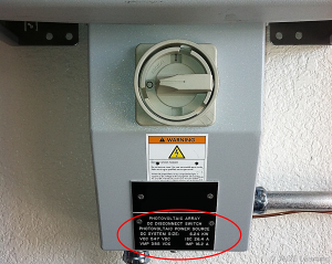
A good set of plans will include these numeric values. If not on the plans, then the installer and inspector will have to gather data from the PV module nameplate and take the number of modules along with the number of parallel connected strings in order to obtain these values. See Figure 5.
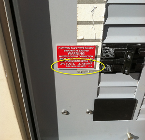
Section 690.54 requires a label at the point where the PV system interconnects to other sources such as the premises wiring system. The label must have the rated ac output current and the nominal operating ac voltage. This rated ac output current can be found on the inverter nameplate. See Figure 6.

Section 705.12(D)(2)(3)(b) requires a warning label to ensure that the backfed overcurrent protection device (OCPD) remains at the opposite end of the main OCPD. See Figure 7. This only applies when the sum of the main OCPD and backfed OCPD exceeds 100% of the busbar rating as allowed by 705.12(D)(2)(3)(b).
There are many other labels that might be required depending on each system design. Be sure to double-check with the AHJ to see if they have other labeling requirements above and beyond the NEC.
To learn more about photovoltaic systems, sign up for a JADE Learning electrical continuing education course: Introduction to PV Systems.