Understanding Box Fill Calculations: Must-Have Knowledge for Installers and Inspectors - NEC 2017, Article 314.16
Published on February 4, 2020 by Robert Key
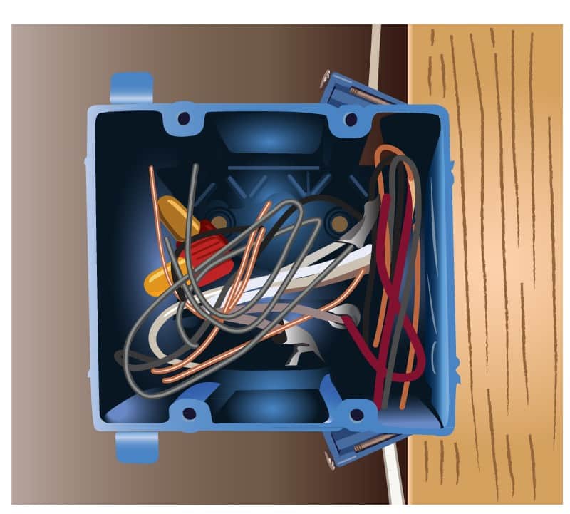
Can you do a box fill calculation at the jobsite? This is an important skill for installers and inspectors alike, since a box that is overfilled can cause a fault, arcing, or even a fire. But how do we determine if a box is overfilled in a real-world situation? There may be visible signs of overcrowding, but you cannot be sure until you do a proper box fill calculation. It is not too difficult once we understand the basics. We will cover the basics for performing a box fill calculation, after which we will walk through a real-world example. It may be helpful to have a calculator available. The tables in this section, 314.16(A) and 314.16(B), are important to have on hand in order to do the volume calculation correctly.
A Volume Allowance for each conductor is counted based on the following:
- One for each conductor (phase conductor or grounded conductor) that terminates or splices within the box.
- One for the largest equipment grounding conductor.
- One for internal cable clamps (one or more) if present.
- Two for each device (outlet or switch).
- One for one or more luminaire studs or hickeys.
- One for a conductor that passes through unbroken.
- Each conductor loop inside a box gets counted twice if longer than 2 times the minimum required length.
That leaves two variables to solve:
What is the volume of the box?
- Table 314.16(A) gives the volume of common metallic boxes. The same table shows how many conductors are allowed in a specific box, but only if they are all the same size.
- Non-metallic boxes and those not found in the table must be legibly marked as to volume if they are 100 cubic inches or less.
How much volume should be counted for each conductor?
(Given in cubic inches, metric equivalents can be found in the table.)
Table 314.16(B) gives the volume per conductor based on size (AWG) of conductor as follows:
- 18 gauge — 1.5 cu.in.
- 16 gauge — 1.75 cu.in.
- 14 gauge — 2.0 cu.in.
- 12 gauge — 2.25 cu.in.
- 10 gauge — 2.5 cu.in.
- 8 gauge — 3.0 cu.in.
- 6 gauge — 5.0 cu.in.
Now we will work through a real-world example.
The electrician has installed a 4" x 1 ½" metallic box. Per Table 314.16(A) this box has a maximum fill volume of 21 cu.in.
The box in question contains:
- Two #12 NM cable (All conductors are spliced or terminated in the box).
- One #14 NM cable.
- Two internal cable clamps.
- One device yoke.
- One stud for mounting a lighting fixture.
- Grounding conductors in each NM cable.
Is this a compliant installation? Let's do the math.
- Two #12 NM cable — Four conductors x 2.25 cu.in. = 9 cu.in.
- One #14 NM cable - Two conductors x 2.00 cu.in. = 4 cu.in.
- Two internal cable clamps — One volume allowance based on largest conductor = 2.25 cu.in.
- One device yoke — Double volume allowance based on largest conductor connected to device x 2.25 cu.in = 4.5 cu.in.
- One stud for mounting a lighting fixture — One volume allowance based on largest conductor = 2.25 cu.in.
- Grounding conductors in each NM cable - One volume allowance based on largest conductor = 2.25 cu.in.
Total volume allowance 9 + 4 + 2.25 + 4.5 + 2.25 + 2.25 = 24.25 cu.in.
This is more than the 21 cu. in. capacity of the box and therefore this installation is not in compliance with NEC 314.16.
There you have it, we have accomplished a proper box fill calculation. There are some additional nuances regarding fixture wires and dividers in this code section, they are less common but still important. Once you have the basic idea in hand, and have memorized the common conductor volumes, it is not too difficult to do these "on the fly". So practice next time you are on the jobsite. It is a great skill to have a handle on, and if you like math, it can actually be fun.