Motor Calculations — Part II: Motor Circuit Conductors
Published on May 21, 2018 by Wes Gubitz
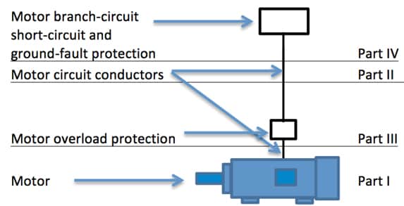
This is the second part of a four-part series designed to help explain how to properly calculate motor circuits. In Part I: The Motor Load, we demonstrated how to determine the motor load for general motor applications, 430.6(A)(1). Table values shall be used to determine the ampacity of conductors... instead of the actual current rating marked on the motor nameplate. The motor full-load current, the current used to determine the ampacity necessary to properly size motor circuit conductors, is found in Article 430 using Tables 430.248 for Single-Phase AC Motors, and 430.250 for Three-Phase AC Motors.
Part II: Motor Circuit Conductors will demonstrate how to size motor circuit conductors.
There are two conditions that must be met when sizing branch circuit conductors, the branch-circuit conductors shall have an ampacity not less than the maximum load to be served after the application of any adjustment or correction factor, 210.19(A)(1), and they shall be protected against overcurrent in accordance with their ampacities, 240.4. Branch circuit conductors must be sized to carry their calculated load and have adequate overcurrent protection.
The following steps are used to size branch circuits, the circuit conductors between the final overcurrent device protecting the circuit and the outlet(s), motor branch circuits included.
1. Determine the load
Noncontinuous (100%)
Continuous (125% multiplier)
Specific Purpose (as instructed)
2. Determine conductor and insulation
Copper
Aluminum
3. Apply general requirements of Article 310
Ambient temperature correction, 310.15(B)(2)(a)
Insulation type/rating, 310.15(B)(16), 310.104(A)
Raceway or cable adjustment factors, 310.15(3)(a)
Determine the allowable ampacity, 310.15(B)(16)
4. Determine equipment terminal rating, 110.14(C)
≤ 100A use 60°C ampacity rating, unless marked for 75°C
> 100A use 75°C ampacity rating
5. Determine conductor using 310.15(B)(16), Allowable Ampacities of Insulated Conductors.
When sizing a motor branch circuit for a single motor, the motor load is determined using the appropriate table and then multiplying that number by 1.25. Article reference 430.22 Single Motor, has determined conductors that supply a single motor used in continuous duty application shall have an ampacity of not less than 125 percent of the motor full-load current rating, as determined by 430.6(A)(1).... A continuous duty motor is treated as a continuous load, a load where the maximum current is expected to continue for three hours or more. Continuous loads have a multiplier of 125% applied when sizing branch circuits and overcurrent protection.
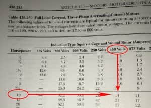
Motor current is determined using the appropriate table in Article 430; this is the motor full-load current value used to determine the minimum allowable ampacity for a single motor branch circuit conductor. For example, the calculated load for a 460V, 3-phase, 10 HP motor is determined using table 430.250, Fig. 2, and the conductors shall have an ampacity of not less than 125% of the motor full load current, or 14A x 1.25 = 17.5A, or 18A, 220.5(B) (See note.).
Let's consider how to apply the steps used for sizing branch-circuits to sizing motor circuit conductors:
Step 1. We have already determined that the table values are used to determine motor full-load currents with a multiplier of 1.25;
Step 2. We typically use copper conductors for motor circuits;
Step 3. The correction and adjustment factors are applied the same for motor circuits as with other circuits;
Step 4. Motors have terminal ratings of 75°C; and
Step 5. Multiply the selected conductor allowable ampacity by all correction and adjustment factors to determine that the calculated value is larger than the calculated motor load.

For example:
What size THWN can be used for a 40 HP, 3-phase, 460V motor with an ambient temperature of 106°F?
Answer: 4AWG.
Solution:
The full-load current for a 40 HP, 3-phase, 460V motor is 52A, 52A x 1.25 = 65A. The correction factor for THWN at 106°F is .82 (See Fig. 3). The corrected ampacity for a 4 AWG THWN copper conductor is 70A, 85A x .82 = 70A.
The corrected ampacity of the 4 AWG THWN of 70A is greater than the calculated motor load at 65A.

Once you understand how to perform the calculation for sizing motor circuit conductors for a single motor, it becomes much easier to understand how to calculate multi-motor circuits and combination loads. These steps are given in 430.24, Several Motors or a Motor(s) and Other Load(s). The conductors shall have an ampacity of not less than the sum of each of the following: 125% of the full-load current of the highest rated motor, the sum of the full-load currents of all other motors in the group, 100% of the non-continuous non-motor loads, and 125% of the continuous non-motor loads.
Parts I and II of this series have explained how to determine the motor load that is used when selecting sizing motor circuit conductors and how to perform the calculations necessary when sizing motor circuit conductors. Part III: Motor Overload Protection will explain how to select the correct overload protection for a typical motor installation. Until then, I encourage each of you to always work toward being a better professional today than you were yesterday. Know your Code.
To learn more, take electrical continuing education online with JADE Learning.