2020 NEC Changes to 430.122 Conductors — Minimum Size and Ampacity
Published on December 2, 2019 by Wes Gubitz
Changes to the 2020 NEC include the addition of several paragraphs in section 430.122. These changes will help the user to determine the correct ampacity for conductors used with power conversion equipment. The Adjustable Speed Drive is one type of power conversion equipment that provides a means of adjusting the speed of an electric motor, 100. A Variable Frequency Drive, VFD, is an adjustable speed drive that controls the speed, the RPM, of a motor by controlling the frequency and voltage supplied to a motor. The changes made in 430.122 Conductors — Minimum Size and Ampacity apply to Adjustable Speed Drive Systems.
Section Part X. Adjustable Speed Drive Systems modifies or supplements Part I — IX of Article 430. The minimum ampacity of the conductors supplying a single adjustable speed drive system has not changed; it is still required to be 125 percent of the rated input current of the drive. The changes made in Section 430.122 have been added to help the user understand and account for the safe installation of these drive systems. Informational Note No. 2 of 430.122(A) provides specific information concerning the affect adjustable speed drives have on the output conductors, the motor leads. The installer must account for the non-typical voltage, current, and frequency outputs of the drive, and the length, spacing and insulation of the conductors used when designing adjustable speed drive systems.
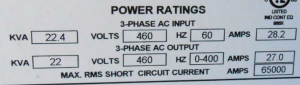
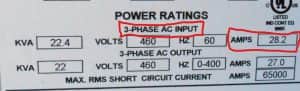
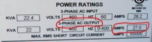
Paragraph 430.122(B) has been added to help clarify how to size the output conductors when using power conversion equipment. The conductors between the drive and the motor shall have an ampacity equal to or larger than 125 percent of the motor full-load current as determined by 430.6(A) or (B). There is an exception to this when the power conversion equipment is listed and marked as "Suitable for Output Motor Conductor Protection."
The exception is that the output conductors shall have an ampacity equal to or greater than the larger of: 430.122(B), 125% of the motor full load current as determined by 430.6(A) or (B); or the ampacity of the minimum conductor size marked on the drive. This exception is followed by an Informational Note that informs the user that the minimum required ampacity of the output conductors is often different than that of the supply conductors.
As with all installations the environmental conditions also need to be considered, and, when installing adjustable speed drives, the maximum output conductor length must be based on the manufacturer's motor lead length restrictions. Failure to follow the manufacturer's maximum motor lead length restrictions or guidelines for single conductor installations can result in poor motor performance and nuisance overload tripping.
The change shown in paragraph 430.122(C) Bypass Device is now a (C) instead of a (B) as in the 2017 NEC to fit the new sequence resulting from the changes of the 2020 NEC.
Paragraph 430.122(D) Several Motors or a Motor and Other Loads has been added to clarify how to calculate the ampacity of conductors when other loads are on the same feeder. The conductors supplying this circuit shall have an ampacity in accordance with 430.24 Several Motors or a Motor(s) and Other Load(s) using the rated input current of the drive in calculating the ampacity.
The changes to Section 430.122 provide the user with a better explanation of what is required when calculating the minimum size and ampacity of the output conductors for an individual adjustable speed drive and how to determine the ampacity of the feed conductors when an adjustable speed drive is added to a circuit with other motors and/or other loads.
JADE Learning offers 2020 NEC continuing education available online in 2020.