PV Systems: The Inverter
Published on March 31, 2015 by JADE Learning
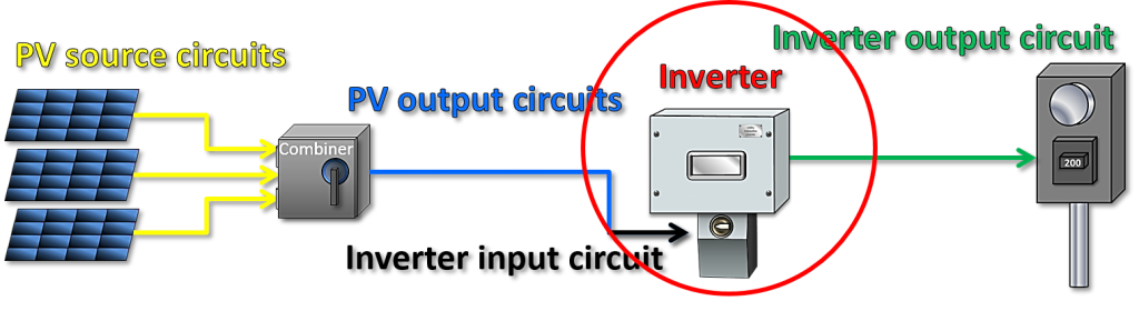
In the previous post, we discussed PV modules which is the first stop in the PV system. Now let's move on to the inverter.
An inverter takes the DC current produced by the PV modules and converts it to AC current for connection to the utility grid.
Inverters have many different features. Some will be only for use on grounded PV systems while others will be for ungrounded systems. Always consult the manufacturer's installation instructions before installing an inverter.
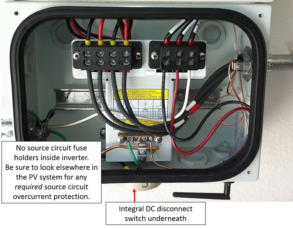
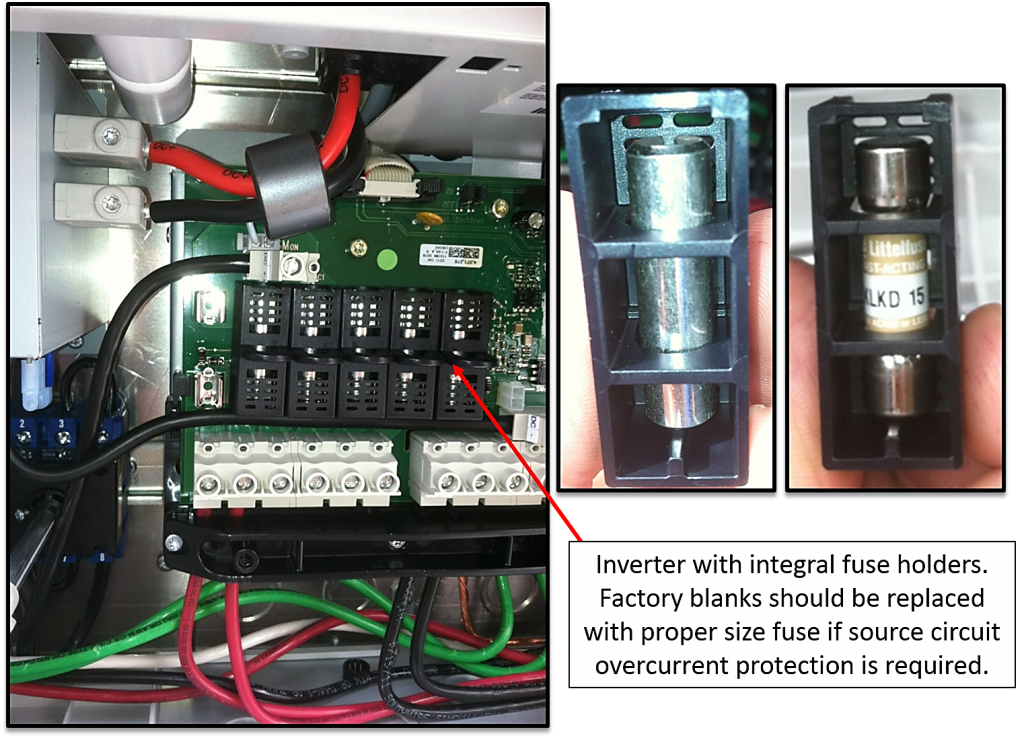
Some inverters have internal fuse holders for the source circuits coming from the PV modules while others may have only a din rail for field installing aftermarket fuse holders. Some inverters have an internal DC disconnect switch that complies with the disconnection requirements in 690.15 while others, that do not, will require a separate DC disconnect switch to be installed in order to comply with the NEC requirement for a DC disconnecting means.
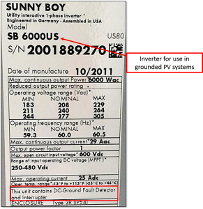
For grounded inverters, the factory marking on the inverter nameplate will make it evident that the inverter is equipped with the required DC Ground-fault detection and interruption feature specified in 690.5(A)
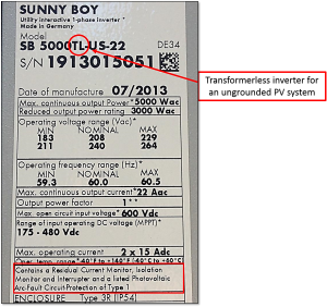
The factory markings on some inverters for use only in ungrounded PV systems will leave you scratching your head wondering if the unit complies with 690.35(C) and has any kind of DC ground-fault protection at all. Often these inverters for ungrounded systems are marked "contains a residual current monitor, isolation monitor and interrupter" but do not actually say the words "ground-fault detection or interruption".
Micro-inverters are also quite common. Micro-inverters are individual inverters (one per module) that are directly attached to each PV module.
The installation instructions on these are quite easy to follow and will tell the installer how many micro-inverters can be used on each 20 amp branch circuit. A common misconception is that by attaching a micro-inverter to a DC PV module, an AC PV module is now created. This is an inaccurate assumption that is often used in order to bypass some of the strict PV source circuit requirements in Article 690 since the source circuit requirements in the article do not apply to AC PV modules (see 690.6(A)).
According to the Article 690 definition, an AC PV module is a complete, environmentally protected unit consisting of solar cells, optics and inverter. Product category QHYZ in the UL White Book tells us that if we are looking at a listed AC PV module then it will be marked with the UL symbol together with the word "LISTED," a control number, and the product name "Utility Interactive AC Module" or "Utility Interactive Inverter Module". Simply put, if these specific markings are absent from the PV module, then we are just looking at a standard DC PV module with a micro-inverter.
To learn more about PV sytems, complete a JADE Learning electrical continuing education course.