2014 NEC 705.12(D)(2) PV Interconnections Part 2
By: JADE Learning | Sep 26, 2014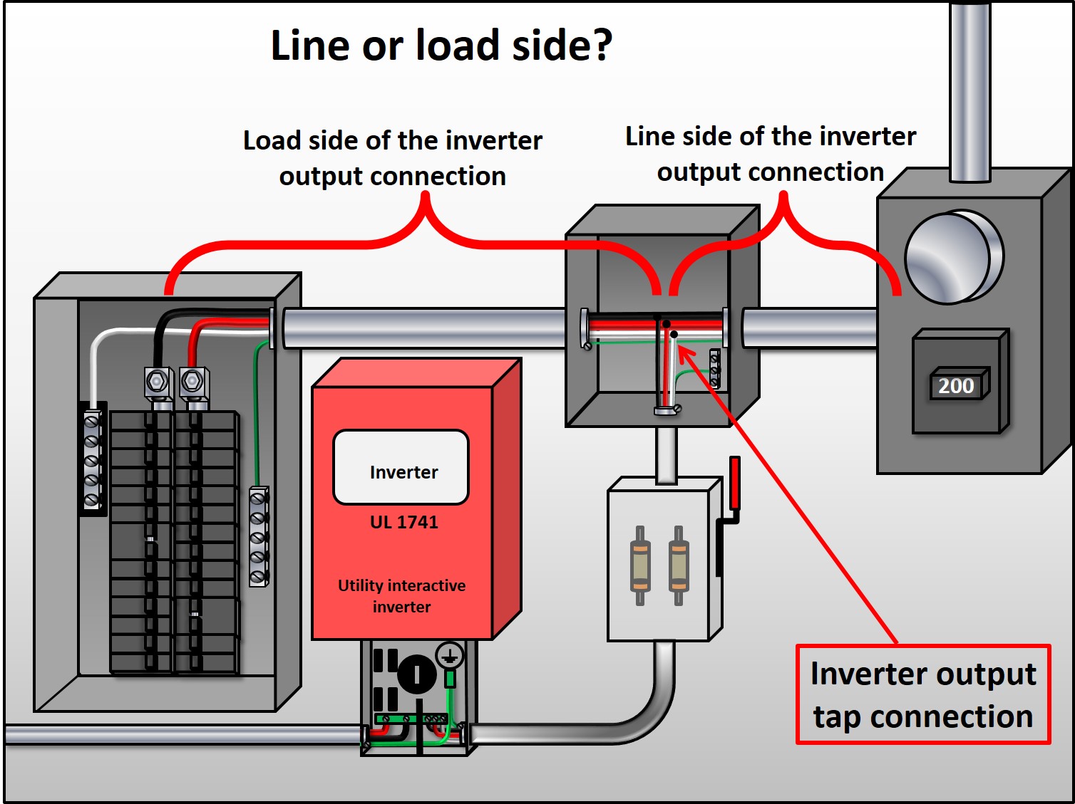
In the previous post we jumped ahead to 705.12(D)(2)(3) to cover the interconnection rules related to busbars since the backfed circuit breaker to busbar connection is most commonly used when connecting a utility interactive PV system to the grid. Now let’s back up a bit to 705.12(D)(2)(1) & (2) and go over the new feeder and tap connection options.
If the point of interconnection will be made at a feeder, other than the opposite end of the primary overcurrent protective device (OCPD), then there are two options and both apply only to the portion of feeder on the load side of the inverter output connection. Before any of the new rules can be applied, it is important to understand which side is the line side and which side is the load side of the inverter output connection (see image 1).
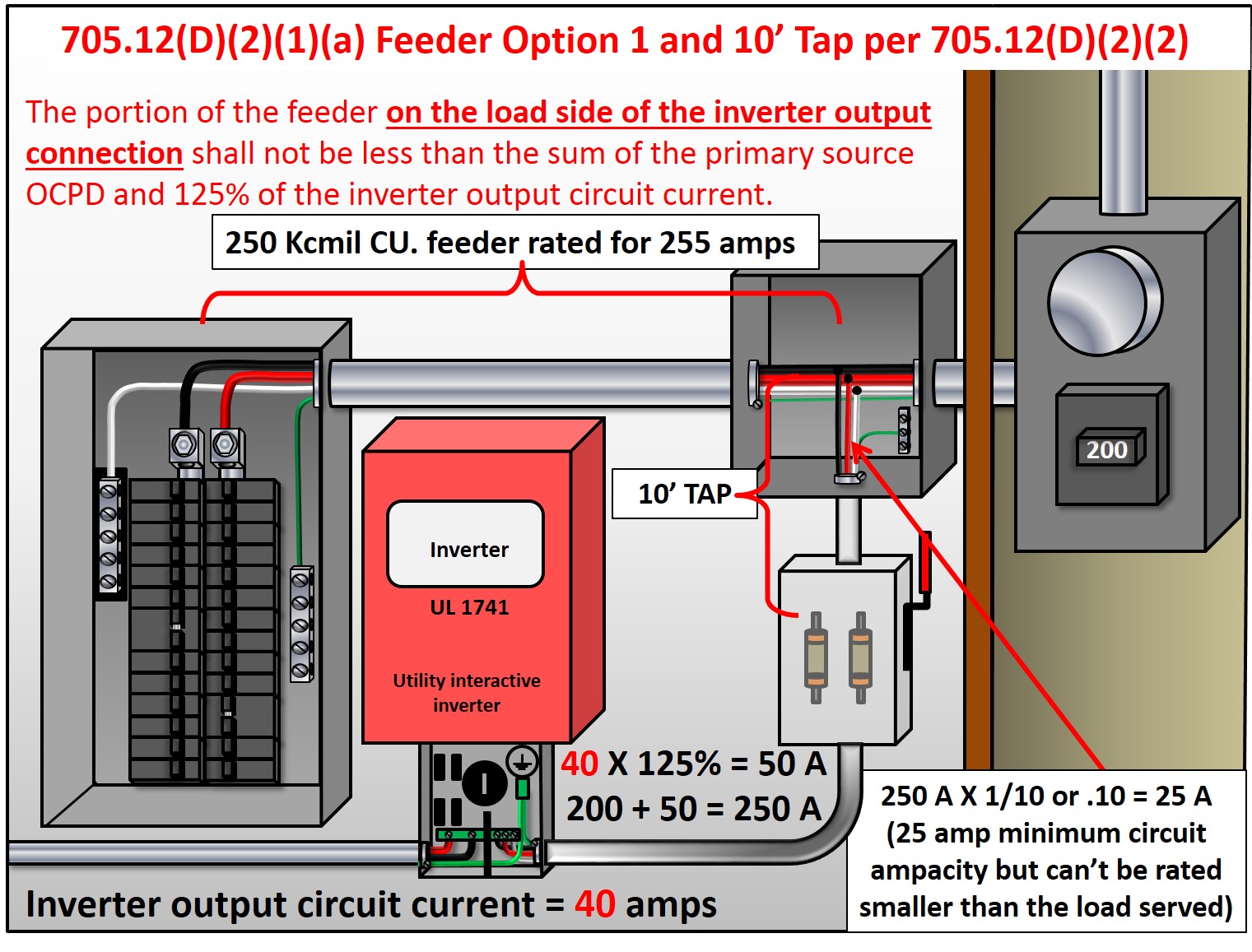
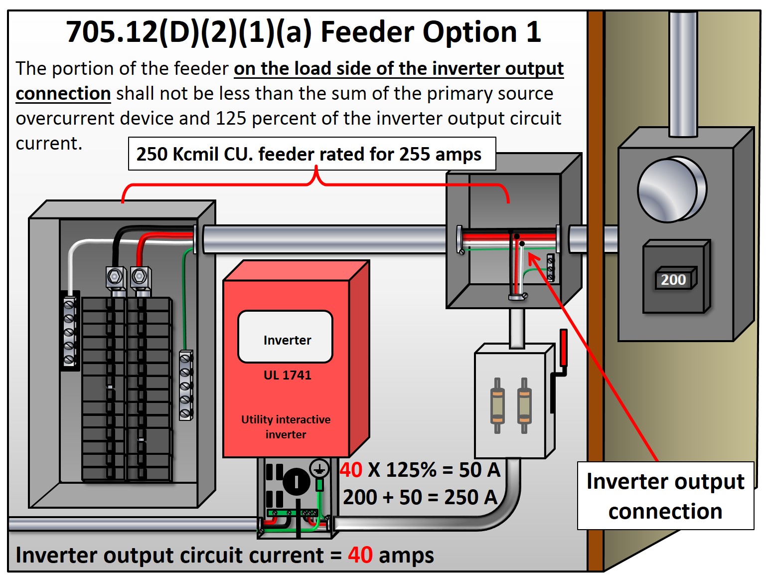
- Option one, 705.12(D)2)(1)(a) (image 2): The section of feeder on the load side of the inverter output connection must be rated no less than the sum of the primary source OCPD and 125% of the inverter output circuit current. The inverter output circuit current is listed on the nameplate of the inverter but can also be calculated by dividing the wattage of the inverter by the applied voltage.
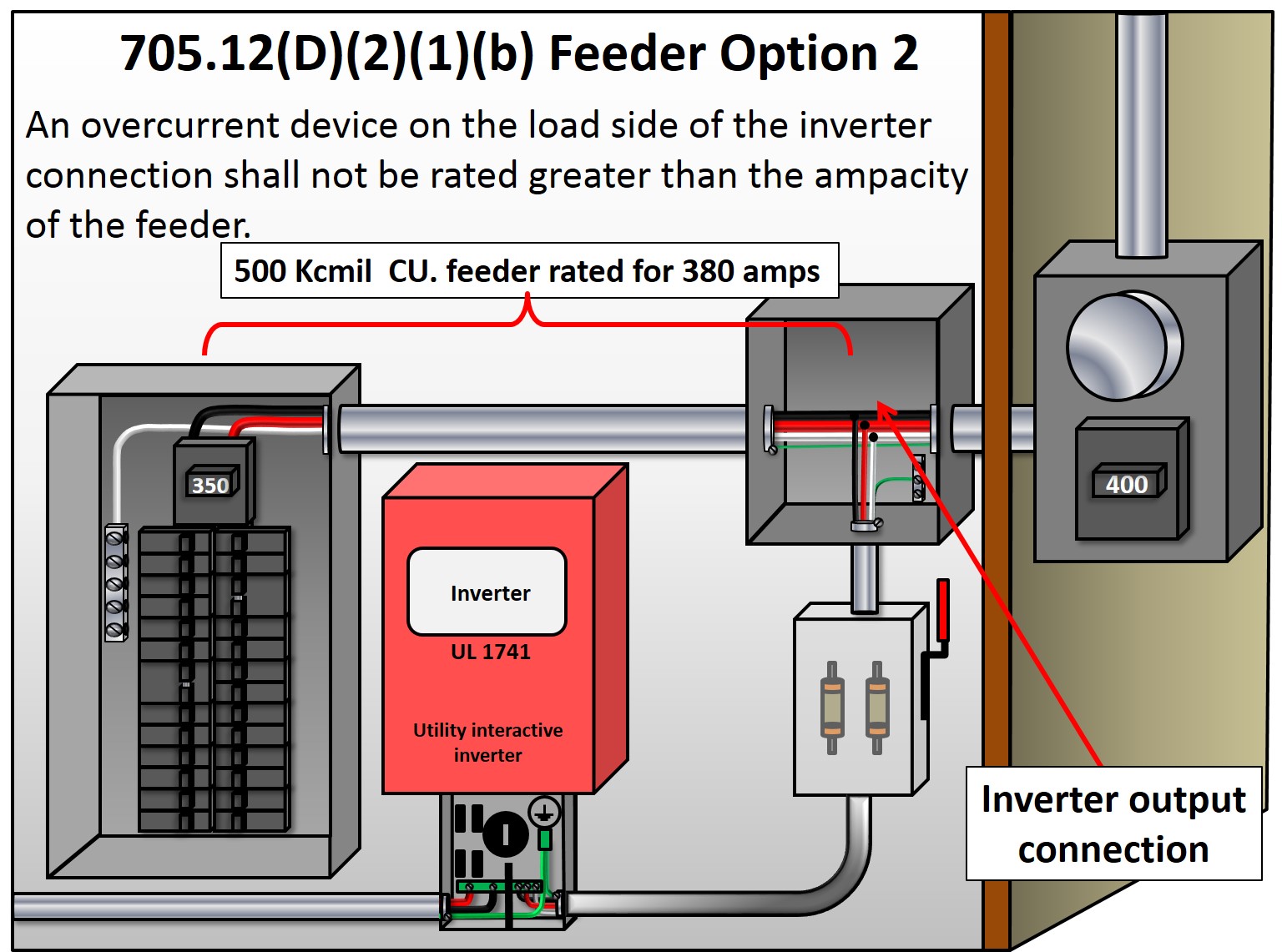
- Option two, 705.12(D)(2)(1)(b) (image 3):An OCPD on the load side of the inverter connection cannot be rated greater than the ampacity of the feeder. Notice in the image that the circuit breaker on the line side of the inverter connection can be rounded up to the next standard size per 240.4(B) in order to protect the 500 kCMIL feeders but the circuit breaker on the load side of the inverter connection cannot.
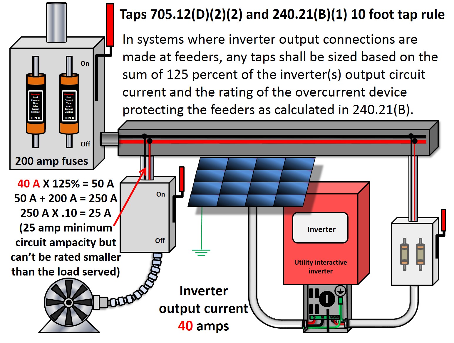
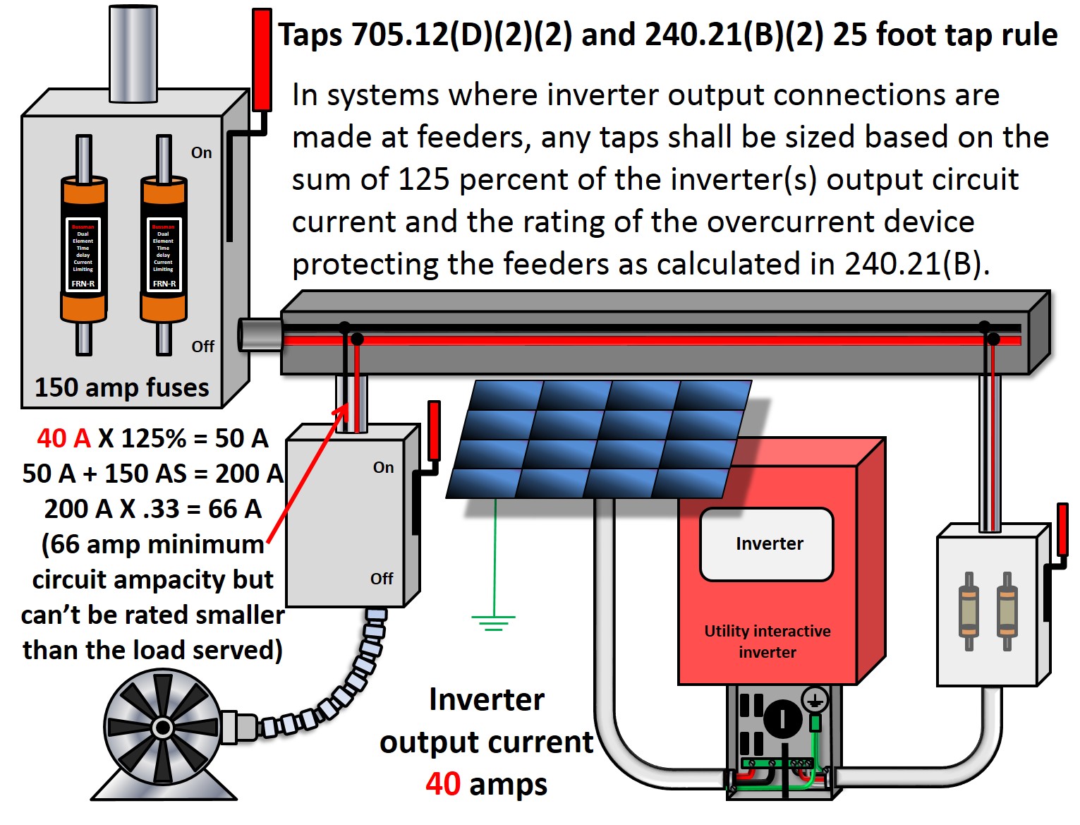
Section 705.12(D)(2)(2) is a short paragraph and covers all taps where PV systems are involved. This includes the tap for the inverter output circuit as well as any other taps off of the same feeder. If the point of interconnection will be made through a feeder tap or to a feeder that also supplies other taps, then all tap conductors must be rated for 125% of the inverter output circuit current plus the sum of the OCPD protecting the feeder being tapped as calculated in 240.21(B). This means that whichever tap rule in 240.21(B) is being used, 125% of the inverter output circuit current must be added to the size of the OCPD protecting the feeder being tapped and then the appropriate tap rule from 240.21(B) can be used. This does not mean that the OCPD protecting the feeder being tapped must be increased in size. The intent is to factor in the contribution from the PV system which increases the amount of current potential on the tap conductors. See the following images for practical tap examples.


The information here is presented very clearly and I appreciate your explanations of the code changes. However, I still cannot determine my current situation: My meter/breaker service entrance (200A main) has a provision for a secondary main breaker (70A max). Would this secondary main be allowed to be used for a 20A OCPD (16A max inverter current) PV interconnection? What special labeling may be required?
Sounds like you might have one of those electric panels that are specifically meant for a PV installation. Eaton cutler Hammer has one that is similar to the one you described.
First, check the installation instructions for the panelboard. Most likely, you will be able to connect up to 70 amps of input from the PV system. As far as labeling goes, for sure you will at least need to provide the labels mentioned in 2014 NEC code sections 690.54 and 690.56 but there might be others (depending on the type of installation).
Question, how many sources of interconnections are you permitted by the 2017 NEC. Example can one utilize a tap interconnection at the line side along with a back-fed breaker interconnection to the busbar all at one residential service. It This would summarize as separate interconnections to one service. It appears that the NEC code is silent as to utilizing multiple PV interconnection sources to one service.