Variable Frequency Drives (VFD) Theory and Troubleshooting
By: David Herres | Apr 09, 2018
By: David Herres –
Variable Frequency Drives (VFD’s), also referred to as Adjustable Speed Drives, are prominent in today’s workplace. They are used in elevator, water pump, high-volume air compressor applications and material-handling systems wherever speed and torque characteristics of AC motors are regulated.
In Thomas Edison’s time, the DC motor was used to produce rotary motion from electrical energy to power equipment in farms, homes, and on the factory floor. The advantage of a DC motor was that the motor speed could be easily and smoothly regulated by adjusting the voltage.
The brushless AC induction motor, invented by Nikola Tesla and introduced into the marketplace by George Westinghouse, was economical to produce and to operate, but the drawback was that its speed could not be efficiently regulated. You could slow it down by reducing the voltage, but this was equivalent to overloading it, resulting in temperature rise and short motor life. Smooth and efficient speed control is essential in many applications, for example elevators, where the car must decelerate prior to stopping at each landing. For many decades, DC motors with rectifiers had to suffice in this and similar installations.
In the 1960’s VFD’s were developed and came to be used world-wide, providing an easy solution to the problem. They control motor speed using pulse width modulation, whereby waveform alteration rather than voltage adjustment is used to slow down or even speed up off-the-shelf induction motors relative to nameplate values, provided shaft bearings and cooling are up to the task.
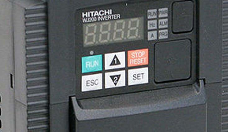
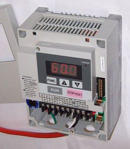
Variable Frequency Drives can be configured to control and report other motor parameters by means of a simple user interface. VFD’s are for the most part reliable and trouble-free, but eventually there is the potential for malfunction, and it is generally the maintenance electrician within a facility who is tasked with making an evaluation and on-site repair. With the right test equipment, trouble-shooting is much simpler than servicing a color TV or a large cooling system. To begin, we’ll look at the anatomy of a typical VFD – a unit that regulates the speed of an assembly-line conveyor.
VFD generally refers to the controller with an operator interface, or to the complete assembly including the motor. The VFD and controller may be housed in a large floor-to-ceiling enclosure located between the operator and the motor-driven equipment, a brick-type unit that will fit in the palm of your hand, or somewhere between these extremes. Sixty-cycle AC power from the utility, typically 480 volts, is fed via a branch circuit with over-current protection to the VFD input where it is first rectified and filtered to create a ripple-free DC. This current is conveyed by the DC bus to the inverter section, where the electrical energy is converted to a square-wave AC whose duty cycle, the ratio of peak voltage to off time, is expressed as a percentage. The width of this pulse determines the speed of the motor, which can be varied so that it is greater or less than nominal.
The waveform at the inverter output is determined manually or automatically by electrical signals from the motion controller and ultimately from the user interface. In the event of equipment malfunction, the first task of the attending electrician is to determine whether the equipment failure is with the VFD or elsewhere in the circuit. Motor problems such as overheating, intermittent operation, excessive current draw causing overload tripping, or short motor life can result from poor power quality at the VFD input, motor fatigue, load binding, or an undersized motor. Another problem could be in one or more of the power supply conductors, such as a faulty termination that could cause a dropped or intermittent phase. Once a fault has been determined to lie within the VFD, some electrical tests are in order.
Voltage measurements can be taken at input, output and on the DC bus. These readings are not always definitive, but in conjunction with a visual inspection they often localize the fault. It must be emphasized that due to the high voltage levels, extreme caution is needed. DC voltage between the VFD front and rear ends, because it is based on peak-to-peak rather than RMS, is higher than the overall equipment AC rating. Specifically, the DC voltage is 1.414 times the RMS AC rating of the overall unit due to the nature of a full-wave rectifier. So, for a 480-volt VFD, we’re looking at 678 volts on the DC bus. Moreover, as in any power supply, the electrolytic capacitors can store a potentially lethal charge long after the unit is powered down.
Much information can be obtained by doing voltage readings on the DC bus. Be sure to wear appropriate PPE and follow electrical safe work practices when checking voltage. All three voltages should be equal with no ripple as measured at the rectifier output or anywhere on the DC bus. All three conductors are referenced to, but float above ground, so it is not safe to check them with a bench-type oscilloscope unless it is equipped with high-voltage differential probes. Since these are costly, many electricians go the route of a hand-held, battery-operated oscilloscope with all inputs isolated from ground and from each other. Lacking an oscilloscope, ripple can be detected using a multimeter in the AC volts mode. If ripple is detected, one or more of the filter capacitors in the rectifier be the source of the problem.
In the rectifier section, any one of the diodes or capacitors can fail, so even if they are not visually defective, they may need to be checked with a multimeter in the diode and capacitor check modes.
In the inverter section, the insulated-gate bipolar transistors (IGBT’s), which are very fast switches, should be checked against one another for equivalent operation, here again preferably with a hand-held oscilloscope. Another failure mode is in the data input, which sets the amount of pulse-width modulation. Manufacturers’ documentation, generally available as a free Internet download, is needed to get anywhere in this department.
Of course, the Variable Frequency Drive (VFD) as well as the entire motor installation must conform to National Electrical Code requirements. VFD’s and other adjustable-speed drive systems are covered by Part X in Article 430. An electrician entrusted with the care of this system should survey all aspects of the equipment with a view to correcting any deficiencies. Points to check in addition to the VFD include but are not limited to the following:
- Motor branch circuit conductors sized in accordance with 430.22.
- Motor Short-circuit and Ground-fault protection- 430.52
- Disconnecting means and controllers must be sized and located with reference to NEC Section 430.110 and Table 430.251(B).
- Motor controllers-Article 430 Part VII.
- Grounding and bonding are required to conform to Articles 250 and 430. Equipment grounding conductors are needed for the VFD, user interface and motor, with verified continuity to the service entrance panel and building grounding system.
As all electricians understand, these are just some basic NEC requirements. The entire installation must conform to all of the applicable requirements in the NEC.
Login to www.JadeLearning.com to learn more about electrical installations and the NEC.

Thanks, it is quite informative