Feeder Conductor Ampacity
By: Dennis Bordeaux | Jan 24, 2017
Feeders Part 3
Feeder Conductor Ampacity.
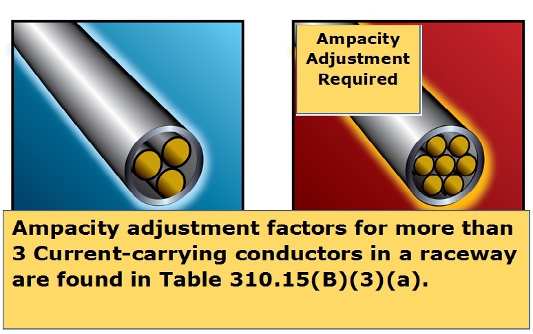
The conditions of use must be considered when determining the minimum size of a feeder conductor. A continuous load, such as the lighting load in a store building, generates heat in the feeder conductor that must be compensated for. Ambient temperatures above 86oF or more than 3 current-carrying conductors in a raceway or cable can have a similar heating effect.
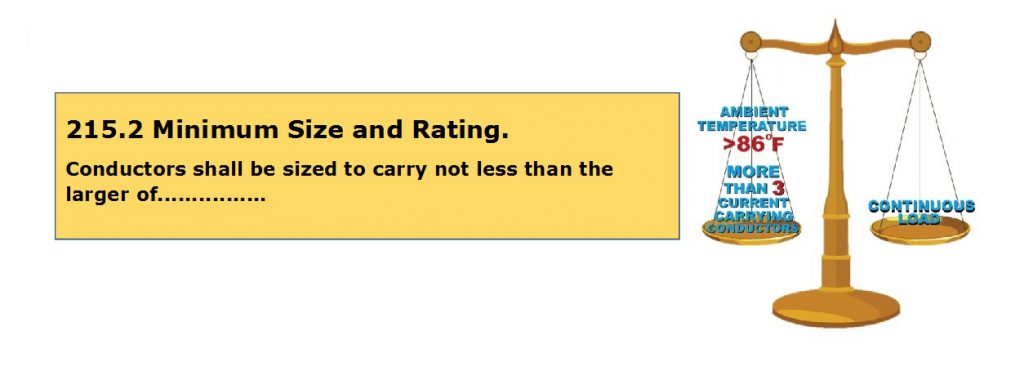
According to 215.2(A)(1) in the 2014 NEC the ampacity of feeder conductors must not be less than the ampacity required for the greater of (A) or (B) below:
(A) 100% of the noncontinuous load plus 125% of any continuous loads.
OR
(B) 100% of the maximum load served after the application of any ampacity adjustment or temperature correction factors.
The ampacity of the feeder conductors is also limited by the temperature rating of the circuit breaker or panelboard terminals as covered in 110.14(C). Equipment terminals for circuits rated over 100 amps will be rated at 750C. Higher temperature rated conductors are permitted to be used on these terminals, but the ampacity of the conductor used is limited to no more than the 750C ampacity in Table 310.15(B)(16) for the same size conductor.
For example, a 208Y/120 volt 4-wire 3-phase feeder supplies 100 amps of continuous nonlinear lighting load and 50 amps of noncontinuous load for general purpose receptacles in a retail store. All terminals and conductors are rated 75oC.
First, find the ampacity of the conductor needed to satisfy 125% of the continuous load plus 100% of the noncontinuous load.
100 Amps continuous X 125% = 125 Amps.
125 Amps + 50 Amps noncontinuous = 175 Amp conductor.
In the 75oC column of Table 310.15(B)(16), a 2/0 AWG THWN copper conductor has an allowable ampacity of 175 amps so this conductor meets the minimum required ampacity for the noncontinuous load plus 125% of the continuous load.
The conductor ampacity in Table 310.15(B)(16) is based on an ambient temperature of 86oF and not more than 3 current-carrying conductors in a raceway. If there are more than 3 current-carrying conductors in a raceway or cable, the ampacity of the conductor must be adjusted.
Since the 208Y/120-volt, 4-wire feeder supplies nonlinear lighting loads, the neutral must be counted as a current carrying conductor per 310.15(B)(5). This means that there are 4 current-carrying conductors in the same raceway. The adjustment factor in Table 310.15(B)(3)(a) for 4-6 current-carrying conductors in the same raceway or cable is 80% or 0.80. The fastest way to find a conductor that will meet the adjusted ampacity requirement is to divide the load served by the adjustment factor (0.80). It is not required to multiply the continuous load by 125% before applying the adjustment factors in Table 310.15(B)(3)(a).
Load served = 100 Amps continuous + 50 Amps noncontinuous = 150 Amps.
150 Amps ÷ 0.80 = 187.5 Amps (Round up to 188 Amps).
In the 75oC column of Table 310.15(B)(16) a 3/0 THWN copper conductor has an allowable ampacity of 200 amps. To double check that this conductor is sufficient for the load served, multiply the conductor ampacity by the 80% adjustment factor (0.80) in Table 310.15(B)(3)(a).
200 Amps (From Table) X 0.80 adjustment factor = 160 Amps adjusted ampacity.
Load served = 100 Amps continuous + 50 Amps noncontinuous = 150 amps.
The adjusted ampacity of a 3/0 THWN copper conductor is adequate for the maximum load served. Since the ampacity adjustment resulted in a conductor larger than the 2/0 AWG THWN conductor required for the noncontinuous load plus 125% of the continuous load, the larger 3/0 THWN copper conductor must be used.
Adjustment factors for more than 3 current-carrying conductors in a raceway or cable also apply where single conductors or multiconductor cables are bundled together for more than 24 inches in length. Although not discussed in this article, conductor ampacity must also be adjusted for ambient temperatures other than 86oF. Ambient temperature correction factors are found in Table 310.15(B)(2)(a).
To learn more about the allowable ampacity of conductors and the NEC, register for one of our on-line courses at jadelearning.com or you can power your career to the next level by signing up for one of our exam prep courses!

I am asking about the 251.2 A (2) (Amapacity Relative to Service Conductor)
” The Feeder Conductor Ampacity shall not be less than that of the Service Conductor where the Feeder conductor Carry the total Load Supplied by Service Conductor with an Ampacity od 55 Amperes or less”
I don’t understand what it mean very well, I am confuse